The size of wire that you need to connect your solar components together will generally depend on 2 variables:
- The maximum amount of current (Amps) that will be flowing through the wire
- The length of the wire
In this article, you’ll learn how these variables come into play, and how you can use them to determine the right size of wire that you need for your 300W solar system.
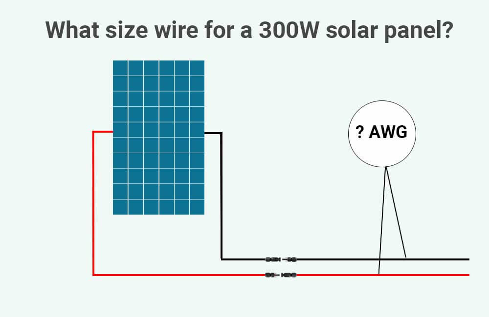
What size cable for 300W solar panel?
As a rule of thumb, if your 300W solar panel is rated at 24 Volts (nominal), and the distance between your solar panel and the solar charge controller is less than 25 feet (7.5m), a 12 AWG Copper wire would generally be sufficient.
If the 300W solar panel is rated at 12 Volts, and the distance between the panel and the charge controller does not exceed 25 feet, you would generally need an 8 AWG wire.
However, when sizing wires, it’s recommended not to rely on general rules of thumb.
You can size the wires between your solar panel and your solar charge controller correctly by following a couple of easy steps.
To make these steps even easier to understand, I’ll use an example of a 24V-300W solar panel that has the following specifications:
- Short-circuit current (Isc): 10.5 Amps
- Optimal operating current (Imp): 9.8 Amps
- Optimal Operating Voltage (Vmp): 32.7 Volts
I’ll also make the assumption that the one-way distance between the solar panel and the solar charge controller is 25 feet.
Let’s get to it.
Step 1: Maximum Current and wire Ampacity
The wire you use for your 300W solar panel should have an Ampacity (in Amps) that is – at least – 156% greater than the short-circuit current of the solar panel. In other words, you’ll need to multiply the short-circuit current (Isc) of your 300W solar panel by 1.56, and then find the wire size that has a greater ampacity than that value.
For example, if the short-circuit current of our 300W solar panel is 10.5 Amps, then:
Wire Ampacity should not be less than = Short-Circuit Current (Amps) x 1.56
Wire Ampacity should not be less than = 10.5 Amps x 1.56
Wire Ampacity should not be less than = 16.38 Amps
We can then use the following table (NEC table 310.16) to choose our Copper wire size:
| Copper Wire Size | 60°C(140°F):
Types TW & UF |
75°C(167°F):
Types RHW, THHW, THW, THWN, XHHW, XHWN, USE, ZW |
90°C(194°F):
Types TBS, SA, SIS, FEP, FEPB, MI, PEA, RHH, RHW-2, THHN, THHW, THW-2, THWN-2, USE-2, XHH, XHHW, XHHW-2, XHWN, XHWN-2, XHHN, Z, ZW-2 |
| 16 AWG | – | – | 18 A |
| 14 AWG | 15 A | 20 A | 25 A |
| 12 AWG | 20 A | 25 A | 30 A |
| 10 AWG | 30 A | 35 A | 40 A |
| 8 AWG | 40 A | 50 A | 55 A |
| 6 AWG | 55 A | 65 A | 75 A |
| 4 AWG | 70 A | 85 A | 95 A |
| 3 AWG | 85 A | 100 A | 115 A |
| 2 AWG | 95 A | 115 A | 130 A |
| 1 AWG | 110 A | 130 A | 145 A |
| 1/0 AWG | 125 A | 150 A | 170 A |
| 2/0 AWG | 145 A | 175 A | 195 A |
| 3/0 AWG | 165 A | 200 A | 225 A |
| 4/0 AWG | 195 A | 230 A | 260 A |
You can see that the table provides 3 columns and 3 ampacity values for each wire gauge. When sizing wires, you can either use the 60°C(140°F) column or the 75°C(167°F) column. So, which column should you use?
Well, the answer is the following:
If every component, and terminal that’s going to be connected to the wires is explicitly rated for 75°C(167°F) or more, use the ampacities in the 75°C(167°F) column. If you’re not sure, use the ampacities in the 60°C(140°F) column.
Let me explain.
Now, the more current flowing through a wire, the higher the temperature of the wire is going to get. This means that the higher the wire’s insulation temperature rating, the higher the Ampacity of the wire.
In other words, the higher the temperature rating of the insulation, the more current the wire can safely carry.
Generally, the wires used in these applications are sunlight resistant and are rated for 90°C(194°F). For example, if you look at the table above, you can see that a 14 AWG copper wire that has an insulation temperature rating of 90°C(194°F), can safely carry up to 25 Amps of current.
However, in order for our 14 AWG wires to carry 25 Amps of current, they’ll have to get as hot as 90°C(194°F), and if anything that’s connected to these wires is not rated for 90°C(194°F), we’re going to have problems.
The safest way to go about this is to size our wires based on the ampacities provided in the 60°C(140°F) column. This way, the wires will never exceed a temperature of 60°C(140°F), and any potential equipment overheating will be prevented.
For simplicity, we’ll just use the ampacities provided in the 60°C(140°F) column for the rest of this example.
Now, we’ve determined that the ampacities of our wires should be more than 16.38 Amps. If we look at the 60°C column of the table, we can see that 12 AWG copper wires can safely carry up to 20 Amps of current, which is perfect for what we need.
We can go higher than 12 AWG if we like (10 or 8 AWG for example), but we can’t go lower.
Please note that if the outdoor temperature in your area goes above 86°F/30°C, you will need to account for that using ampacity temperature correction factors. Read more about this in our complete Solar panel to charge controller wire sizing guide.
In any case, now that we know our wires cannot be any smaller than 12 AWG, we’ll also need to account for the voltage drop. This brings us to the next step.
Step 2: Wire length and Voltage Drop
The thickness and length of the wires you use for your 300W solar panel will determine how big of a voltage drop you’ll have between your solar panel and your solar charge controller. The longer and thinner the wires, the bigger the voltage drop.
And the bigger the voltage drop, the less energy you can get out of the solar panel.
Reversibly, you can limit the voltage drop between these components to a recommended 3% by choosing the right size of wires. This can be done through the following formula:
Wire thickness (in Circular Mills) = (12.96 x Operating Current (Amps) x 2 x One-Way Wire Length (feet)) ÷ (0.03 x Operating Voltage (Volts))
Using this formula, you can calculate the cross-sectional area of the copper wire required to limit the voltage drop between your solar panels and the solar charge controller to 3%.
The cross-sectional area of the wire will be calculated in Circular Mills (C.M), and you can then use the following table to determine the wire size in AWG or mm².
| Wire size (AWG) | Wire size (Circular Mills) | Wire size (mm²) |
| 14 AWG | 4110 | 2.1 |
| 12 AWG | 6530 | 3.3 |
| 10 AWG | 10380 | 5.3 |
| 8 AWG | 16510 | 8.4 |
| 6 AWG | 26240 | 13.3 |
| 4 AWG | 41740 | 21.1 |
| 3 AWG | 52620 | 26.7 |
| 2 AWG | 66360 | 33.6 |
| 1 AWG | 83690 | 42.4 |
| 1/0 AWG | 105600 | 53.5 |
| 2/0 AWG | 133100 | 67.4 |
| 3/0 AWG | 167800 | 85 |
| 4/0 AWG | 211600 | 107.2 |
Our variables are:
- Operating Current (Amps): The operating current of your solar panel will be its rated Imp (Optimal Operating Current). In our example, the Imp is 9.8 Amps.
- One-way Wire Length (feet): This is the one-way length of our conductors (One-way wire length = positive wire length = negative wire length). In our example, the one-way wire length is 25 feet.
- Operating Voltage (Volts): The operating voltage of your solar panel will be its rated Vmp (Optimal Operating Voltage). In our example, the Vmp is 32.7 Volts.
Let’s calculate the required cross-sectional area of our wires:
Wire thickness (in Circular Mills) = (12.96 x Operating Current (Amps) x 2 x One-Way Wire Length (feet)) ÷ (0.03 x Operating Voltage (Volts))
Wire thickness (in Circular Mills) = (12.96 x 9.8 Amps x 2 x 25 feet) ÷ (0.03 x 32.7 Volts)
Wire thickness (in Circular Mills) = (6350.4) ÷ (0.98)
Wire thickness (in Circular Mills) = 6480 C.M
If you look at the table, you can see that a 12 AWG wire has a cross-sectional area of 6530 C.M, which is slightly greater than what we need. This means that we don’t need to go above 12 AWG for our setup.
So, for our 24V-300W solar panel, which is 25 feet away from the solar charge controller, we would need 50 feet of 12 AWG copper wire (25 feet for the positive, and 25 feet for the negative).
If the distance between our solar panel and the charge controller had been a little higher (30 feet for example), or if we wanted to further decrease the voltage drop (to 2% for example), we would have needed to use 10 AWG wires instead of 12.
What size wire between the charge controller and the battery?
The following calculator will provide the correct size of copper wires that you need to connect the output of your charge controller to the battery bank:
Feel free to take a look at a couple of examples here.
If you haven’t sized the solar charge controller yet, feel free to use our MPPT solar charge controller calculator.
What size wire from the battery bank to the inverter?
The following calculator will provide the correct size of copper wires that you need to connect your battery bank to the inverter:
If you’re interested in doing the calculations yourself, you can read up more on the subject here.
Related Topics:
What size fuse between solar panels and solar charge controller?