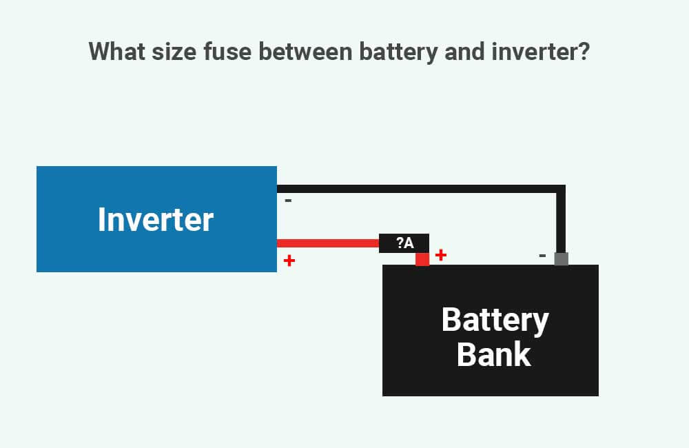
The size of the fuse that you use between your battery and inverter will depend on:
- The amount of current (Amps) that you’d like the inverter to be able to pull from the battery.
- The amount of current that the wire between your inverter and battery can safely conduct.
In this article, I’m going to discuss why fuses (and other overcurrent protection devices) are important, and I’m going to show you how you can use the ratings of your battery, inverter, and wire, to determine the correct size of fuse that you need.

Do I need a fuse between battery and inverter?
The short answer is yes, you do need a fuse (or a circuit breaker) between your battery bank and inverter. If an overcurrent occurs, a fuse between your battery and inverter would blow immediately, which would disconnect the circuit, and therefore protect your battery, inverter, and wiring.
Overcurrent can be due to short circuits, incorrect wiring and wire sizing, excessive load, etc., and can potentially cause permanent damage to your equipment, fire, or even explosions.

Placing a fuse, or an overcurrent protection device in general, that is sized correctly, between the battery and the inverter, would prevent any potential damages caused by overcurrent.
What size fuse between battery and inverter?
Fuses are rated in Amps, and the amp rating of the fuse that you place between your battery and inverter should be no less than 1.25 times the maximum amount of continuous current your inverter is capable of drawing from the battery at the lowest battery voltage, and equal to or lower than the Ampacity of the wire between the battery and the inverter.
For example, if your maximum current is 30 amps, and you’re using an 8 AWG (8.4mm²) Copper wire, which can handle up to 40 Amps of current (@ an insulation rating of 140°F(60°C)), a good fuse size would be 40 Amps.
So, there are really 2 steps to sizing the fuse correctly:
- Step 1: determine the maximum amount of current your inverter is going to pull (at the lowest battery voltage) and multiply it by 1.25 to find the size of the fuse.
- Step 2: compare this calculated fuse size to the ampacity of the wire you’re using.
Calculating the required fuse size:
The maximum amount of current that your inverter uses can be determined using the following formula:
Maximum Amp Draw @ lowest battery Voltage (Amps) = (Inverter’s Continuous Power rating (Watts) ÷ Lowest Battery Voltage (Volts)) ÷ Inverter Efficiency (%) @ max. load
- Inverter’s Continuous Power rating (Watts): This is the maximum amount of continuous power (in Watts) that your inverter is rated for. Not to confuse with the surge power rating of the inverter.
- Battery Voltage (Volts): This is the lowest voltage your battery bank can operate at before disconnecting. By default, the lowest operational voltages of a 12V, 24V, and 48V battery bank, are (respectively) 10V, 20V, and 40 Volts. However, if you have some means of programming the Low Voltage Disconnect (LVD) to a higher value, use that to calculate the maximum amp draw.
- Inverter efficiency (%) @ max. load: Inverters are not 100% efficient, which means they pull more power out of the battery than they deliver to the appliances. The efficiency of the inverter will depend on the inverter, but generally, you should expect around 85% (0.85) efficiency at maximum load.
Once you’ve calculated the maximum amp draw, multiply it by 1.25 to find the fuse amp rating:
Fuse Size (Amps) = Maximum Amp Draw @ lowest battery Voltage (Amps) x 1.25
For example:
Let’s say you have 2 12V-100Ah batteries connected in series, which would make a 24V battery bank. The lowest voltage at which this battery bank can operate is 20 Volts.
And let’s say you’re going to connect this battery bank to a 1000W inverter (Continuous power rating = 1000 Watts).
The maximum amp draw @ the lowest battery voltage can be calculated as such:
Maximum Amp Draw @ lowest battery Voltage (Amps) = (Inverter’s Continuous Power rating (Watts) ÷ Lowest Battery Voltage (Volts)) ÷ Inverter Efficiency @ max. load (%)
Maximum Amp Draw @ lowest battery Voltage (Amps) = (1000 Watts ÷ 20 Volts) ÷ 0.85
Maximum Amp Draw @ lowest battery Voltage (Amps) = (50 Amps) ÷ 0.85
Maximum Amp Draw @ lowest battery Voltage (Amps) = 58.8 Amps
To determine the fuse size, we need to multiply this value by 1.25:
Fuse Size (Amps) = Maximum Amp Draw @ lowest battery Voltage (Amps) x 1.25
Fuse Size (Amps) = 73.5 Amps
Now, fuses have the following standard ratings (in Amps): 10, 15, 20, 25, 30, 35, 40, 45, 50, 60, 70, 80, 90, 100, 110, 125, 150, 175, 200, 225, 250, 300, 350, 400, 450, 500, 600, 700, 800, 1000, 1200, 1600, 2000, 2500, 3000, 4000 5000, and 6000 Amps.
The fuse size you determine using our formulas will likely not exactly match these standard ratings. But all you have to do is find the next higher fuse amp rating.
For example, in our case, the next higher fuse amp rating is 80 Amps.
Now, we’ll need to compare this fuse size to the ampacity of our wire.
Fuse size and wire ampacity:
The amp rating of the fuse you use between your battery bank and inverter should logically not exceed the Ampacity of the wire between the battery bank and the inverter.
But, what is wire ampacity?
Simply put, the Ampacity of a wire is the maximum amount of current (in Amps) that the wire can safely conduct. At a given ambient temperature (86°F/30°C for example) The ampacity of a wire will depend on its thickness (in AWG or mm²), and the temperature that its insulation is rated for.
The more current flowing through the wire, the higher the temperature of the wire. Some wire insulations are more heat-resistant than others and therefore allow for more current to flow through the wire.
At an ambient temperature of 30°C/86°F, here are the allowable Ampacities of different copper wire sizes, for different insulation temperature ratings, based on NEC’s table 310.16:
| Copper Wire Size | Ampacity @ 60°C(140°F) (Amps) | Ampacity @ 75°C(167°F) (Amps) | Ampacity @ 90°C(194°F) (Amps) |
| 14 AWG | 15 A | 20 A | 25 A |
| 12 AWG | 20 A | 25 A | 30 A |
| 10 AWG | 30 A | 35 A | 40 A |
| 8 AWG | 40 A | 50 A | 55 A |
| 6 AWG | 55 A | 65 A | 75 A |
| 4 AWG | 70 A | 85 A | 95 A |
| 3 AWG | 85 A | 100 A | 115 A |
| 2 AWG | 95 A | 115 A | 130 A |
| 1 AWG | 110 A | 130 A | 145 A |
| 1/0 AWG | 125 A | 150 A | 170 A |
| 2/0 AWG | 145 A | 175 A | 195 A |
| 3/0 AWG | 165 A | 200 A | 225 A |
| 4/0 AWG | 195 A | 230 A | 260 A |
When you determine the size of the fuse that you need, make sure the amp rating of the fuse is lower than or equal to the ampacity of the wire you’re using.
If the amp rating of the fuse is higher than the ampacity of the wire you’re using, it means that you’ll need a thicker wire. To size the wire between your battery and inverter correctly, feel free to use our battery-to-inverter wire size calculator.
For example:
Following our previous example, we’ve determined that we would need an 80A fuse between our battery bank and inverter.
I made the assumption that the terminals of our 24V battery bank are 7 feet away from the terminals of our 1000W inverter, and I used our Battery to inverter wire size calculator and determined that I would need a 3 AWG copper wire for this setup.
A 3 AWG copper wire can handle 85Amps or more depending on the temperature rating of its insulation.
Again, if you haven’t sized the wire that you need between your battery and inverter, please refer to the following page: What size wire from battery to inverter?


Thank you for explaining in so much details