In this article, I explain how to correctly size the wires that you need to connect your solar panels to your charge controller.
After reading this, you’ll learn about wire size and ampacity, wire insulation, electrical codes for sizing these wires, temperature correction factors, etc…To make this guide digestible, I’ll illustrate this sizing process through examples.
What size wire from solar panels to charge controller?
To size the wires between your solar panels and solar charge controller correctly, you’ll need to make sure that the ampacity of each wire is at least 1.25 greater than the maximum current going through the wire, and that the total voltage drop between your solar panels and solar charge controller does not exceed 3%.
In other words, the size of the wire must meet 2 conditions:
- Condition 1: The Ampacity of the wire must be at least 125% greater than the Maximum Current.
- Condition 2: The wire must be thick enough to limit the voltage drop between the solar panels and the solar charge controller to 3%.
Let me explain each of these separately.
1- Determining wire Ampacity based on the Maximum Current.
Wire Ampacity is the amount of current that a wire can safely conduct, and it depends on the size of the wire (2 AWG for example), the temperature rating of its insulation (75°C for example), and the ambient temperature in which the wire is conducting current.
The bigger the wire, the more current it’ll be able to carry. And the more current a wire carries, the hotter it’s going to get, so the higher the insulation temperature rating of the wire, the more current it can safely carry.
Now, according to the American National Electrical Code (NEC), Article 690.9(B), and as mentioned above, the ampacity of the wire should not be less than 125% of the maximum current going through the wire.
So, how do you determine the Maximum Current?
According to NEC 690.8 (A), the maximum current is determined by multiplying the short-circuit current by 1.25:
Maximum Current (Amps) = Short-circuit Current (Amps) x 1.25
For example, if you’re trying to size the wire needed to connect a string of solar panels to the solar charge controller, and the short-circuit current of the string is 9 amps, the maximum current is calculated as such:
Maximum Current (Amps) = Short-circuit Current (Amps) x 1.25
Maximum Current (Amps) = 9 Amps x 1.25
Maximum Current (Amps) = 11.25 Amps
You’ll then have to make sure the ampacity of the wire is at least 125% greater than this maximum current:
Wire Ampacity should not be less than = Maximum Current (Amps) x 1.25
Wire Ampacity should not be less than = 11.25 Amps x 1.25
Wire Ampacity should not be less than = 14.06 Amps
So, now that we know that the ampacity of our wire has to be equal to or greater than 14.06 Amps, we can look at NEC table 310.16 to see what size wire meets this condition.
NEC table 310.16 provides Copper wire ampacities based on insulation temperature ratings, and wire size, for a maximum ambient temperature of 86°F (30°C):
| Copper Wire Size | 60°C(140°F):
Types TW & UF |
75°C(167°F):
Types RHW, THHW, THW, THWN, XHHW, XHWN, USE, ZW |
90°C(194°F):
Types TBS, SA, SIS, FEP, FEPB, MI, PEA, RHH, RHW-2, THHN, THHW, THW-2, THWN-2, USE-2, XHH, XHHW, XHHW-2, XHWN, XHWN-2, XHHN, Z, ZW-2 |
| 16 AWG | – | – | 18 A |
| 14 AWG | 15 A | 20 A | 25 A |
| 12 AWG | 20 A | 25 A | 30 A |
| 10 AWG | 30 A | 35 A | 40 A |
| 8 AWG | 40 A | 50 A | 55 A |
| 6 AWG | 55 A | 65 A | 75 A |
| 4 AWG | 70 A | 85 A | 95 A |
| 3 AWG | 85 A | 100 A | 115 A |
| 2 AWG | 95 A | 115 A | 130 A |
| 1 AWG | 110 A | 130 A | 145 A |
| 1/0 AWG | 125 A | 150 A | 170 A |
| 2/0 AWG | 145 A | 175 A | 195 A |
| 3/0 AWG | 165 A | 200 A | 225 A |
| 4/0 AWG | 195 A | 230 A | 260 A |
Now, the table shows 3 different columns, with each column specifying the ampacity of copper wires for a different insulation temperature rating. So, which column to use?
The NEC 110.14 (C) tells us that for equipment rated 100 Amps or less, the 60°C column should be used, even if the insulation of the wire that you’ll be using is rated for higher temperatures. For equipment rated for more than 100 Amps, you can use the 75°C column.
This is to limit the temperature of the conductor and therefore protect the terminals and the connectors from overheating.
So, unless all the components of your system are explicitly rated for 75°C(167°F) or more, use the 60°C(140°F) column. If they are rated for 75°C or more, use the 75°C column.
For example, let’s assume that you’ve made sure that anything that’s going to be connected to the wire is rated for 75°C or more.
If we look at the 75°C column of the table, we can see that a 14 AWG copper wire has an ampacity of 20 Amps, which is more than the 14.06 Amps calculated earlier.
However, the ampacity table above provides ampacities for a maximum ambient temperature of 86°F (30°C). This means that these ampacities are only accurate if the temperature around the wires does not exceed 86°F (30°C), but since these wires are going to be outdoors, chances are the temperature around the wire will get higher than that.
The higher the temperature around the wires is, the less current they’ll be able to safely carry. So, you’ll need to correct these ampacities before you choose the size of the wire.
But, how do you do that?
Well, you can do this by answering the following questions:
1- Are the wires you’re trying to size going to run through a conduit? If yes, how many wires will be running through this conduit?
If the wires you’re trying to size will be running through a conduit, and there will be more than 3 wires running through that conduit, you’ll need to adjust the ampacities in NEC table 310.16 by the conduit fill correction factors provided in NEC Table 310.15 (C) (1):
| Number of wires in conduit | Correction Factor |
| 4-6 | 0.8 |
| 7-9 | 0.7 |
| 10-20 | 0.5 |
| 21-30 | 0.45 |
| 31-40 | 0.4 |
| 41 and above | 0.35 |
For example, let’s say you’re trying to connect 2 strings of solar panels to 2 different charge controllers. This means that there’ll be 4 wires going through the conduit, 2 positives, and 2 negatives. This will increase the temperature around these wires and therefore reduce their ampacities.
Before you choose the size of these wires, you’ll need to multiply the ampacities in NEC table 310.16 by a factor of 0.8.
If, for example, there were 4 separate strings of solar panels, and therefore 8 wires going through the conduit, you would have to use a factor of 0.7.
If the wires you’re trying to size will not be running through a conduit, or they are but are fewer than 4 wires, you don’t have to worry about these conduit fill correction factors.
2- What is the maximum outdoor temperature that these wires are going to be exposed to?
As mentioned above, a higher temperature means lower wire ampacity. So to size your wires correctly, you’ll have to make sure that they are sized in a way that even in higher-than-usual temperatures, the wires can still conduct current safely.
You can determine this maximum outdoor temperature by accessing weather history data in your location.
This maximum outdoor temperature, or ambient temperature, is necessary to adjust the ampacities provided in NEC table 310.16, and therefore choose the right wire size.
3- Are your solar panels installed on the roof?
NEC 310.15 (B) (2) states that for wires or conduits that are exposed to direct sunlight on or above rooftops where the distance between the surface of the rooftop and the wire or the bottom of the conduit is less than 19mm (3-quarters of an inch), a temperature adder of 33°C (60°F) should be added to the outdoor temperature to determine the applicable ambient temperature.
So, for example, if the maximum outdoor temperature that we’ve just determined is 40°C (104°F), and we’re trying to size wires for a roof-mounted system, and these wires will be running through a conduit, and the conduit is less than 0.75 inches above the surface of the roof, the temperature that we’ll need to adjust for is not 40°C (104°F), but 73°C (164°F).
Here are some exceptions where you don’t have to use this temperature adder:
- If your solar panels are ground-mounted.
- If your solar panels are roof-mounted but the conduit is more than 0.75 inches above the surface of the roof.
- If the wires you’re trying to size are not exposed to direct sunlight (wires from the solar panels to the combiner for example).
- If you’re using XHHW-2 type of wires.
In any case, once you have the ambient temperature that you need to adjust for, you can use the temperature correction factors provided in NEC table 310.15 (B) (1) (1) to correct the ampacities in NEC table 310.16.
NEC Table 310.15 (B) (1):
| Ambient Temperature | 60°C(140°F):
Types TW & UF |
75°C(167°F):
Types RHW, THHW, THW, THWN, XHHW, XHWN, USE, ZW |
90°C(194°F):
Types TBS, SA, SIS, FEP, FEPB, MI, PEA, RHH, RHW-2, THHN, THHW, THW-2, THWN-2, USE-2, XHH, XHHW, XHHW-2, XHWN, XHWN-2, XHHN, Z, ZW-2 |
| 10°C (50°F) or less | 1.29 | 1.2 | 1.15 |
| 11°C (51°F) – 15°C (59°F) | 1.22 | 1.15 | 1.12 |
| 16°C (60°F) – 20°C (68°F) | 1.15 | 1.11 | 1.08 |
| 21°C (69°F) – 25°C (77°F) | 1.08 | 1.05 | 1.04 |
| 26°C (78°F) – 30°C (86°F) | 1 | 1 | 1 |
| 31°C (87°F) – 35°C (95°F) | 0.91 | 0.94 | 0.96 |
| 36°C (96°F) – 40°C (104°F) | 0.82 | 0.88 | 0.91 |
| 41°C (105°F) – 45°C (113°F) | 0.71 | 0.82 | 0.87 |
| 46°C (114°F) – 50°C (122°F) | 0.58 | 0.75 | 0.82 |
| 51°C (123°F) – 55°C (131°F) | 0.41 | 0.67 | 0.76 |
| 56°C (132°F) – 60°C (140°F) | – | 0.58 | 0.71 |
| 61°C (141°F) – 65°C (149°F) | – | 0.47 | 0.65 |
| 66°C (150°F) – 70°C (158°F) | – | 0.33 | 0.58 |
Now, to give an example, let’s assume the following:
- The ampacity of our wires cannot be less than 14.06 Amps.
- We’ll have 4 wires running through a conduit.
- The solar panels are ground-mounted.
- The maximum ambient (outdoor) temperature is 40°C (104°F).
- All the connections and terminals of the equipment are rated for 75°C (167°F) or more.
Since we’re certain that every component that’s going to be connected to our wires is rated for 75°C (167°F) or more, we’ll use the 75°C (167°F) columns of these tables.
If we look at NEC table 310.16 (wire ampacity table), at the 75°C (167°F) column, we can see that 14 AWG copper wires are capable of carrying up to 20 Amps.
However, since our wires are going to be inside a conduit, and we have 4 wires, we need to adjust this ampacity (20 Amps) by a factor of 0.8:
Conduit Fill Adjusted Wire Ampacity (Amps) = Wire ampacity (Amps) x 0.8
Conduit Fill Adjusted Wire Ampacity (Amps) = 20 Amps x 0.8
Conduit Fill Adjusted Wire Ampacity (Amps) = 16 Amps
Our system is ground-mounted, so we don’t have to worry about any temperature adders. However, our maximum ambient temperature is 40°C (104°F) (exceeds 30°C (86°F)), so we’ll have to adjust for that.
If we look at NEC table 310.15 (B)(1)(1) (the temperature adjustment factors table), at the 75°C (167°F) column, we can see that for temperatures between 36°C (96°F) and 40°C (104°F), an adjustment factor of 0.88 must be used.
After adjusting the ampacity of our wires for conduit fill, we’ve determined that their ampacity becomes 16 Amps. We’ll use this new ampacity to further adjust for the the ambient temperature:
Temperature Adjusted Wire Ampacity (Amps) = Conduit Fill Adjusted Wire ampacity (Amps) x 0.88
Temperature Adjusted Wire Ampacity (Amps) = 16 Amps x 0.88
Temperature Adjusted Wire Ampacity (Amps) = 14.08 Amps
So, under all of these conditions, our 14 AWG wire can handle up to 14.08 Amps of current without exceeding the 75°C (167°F) temperature limit.
Since we need our wires to be able to handle 14.06 Amps or more, 14 AWG is almost exactly the size of wire that we need. This means that our wires cannot be any smaller than 14 AWG.
If the temperature-adjusted wire ampacity had been a little lower, we would have had to go for 12 AWG wires.
Now that we’ve found the size of the wire that can carry 125% or more of our maximum current, we’ll need to account for the voltage drop.
This brings us to condition number 2.
1- Limiting the voltage drop between the solar panels and the solar charge controller.
In other words, if your wires are too thin and too long, the voltage from the source is going to drop dramatically, hence the term Voltage Drop. Aside from the resulting losses in energy, if the voltage drop is too high, your solar charge controller might not even be able to operate.
Using this formula, we’ll be able to calculate the required cross-sectional area (in Circular Mills) of the copper wire that’ll limit the voltage drop to the desired value. We would then translate this wire size in Circular Mills to the wire size in AWG or mm² using the following table:
| Wire size (AWG) | Wire size (Circular Mills) | Wire size (mm²) |
| 14 AWG | 4110 | 2.1 |
| 12 AWG | 6530 | 3.3 |
| 10 AWG | 10380 | 5.3 |
| 8 AWG | 16510 | 8.4 |
| 6 AWG | 26240 | 13.3 |
| 4 AWG | 41740 | 21.1 |
| 3 AWG | 52620 | 26.7 |
| 2 AWG | 66360 | 33.6 |
| 1 AWG | 83690 | 42.4 |
| 1/0 AWG | 105600 | 53.5 |
| 2/0 AWG | 133100 | 67.4 |
| 3/0 AWG | 167800 | 85 |
| 4/0 AWG | 211600 | 107.2 |
In general, it is recommended that the voltage drop between the solar panels and the charge controller does not exceed 3%.
Now, there are probably going to be 2 types of wires connecting your solar panels to your solar charge controller:
- PV or USE-2 type wires connecting your solar panels to the combiner box or pass-through box. These are referred to as PV source wires.
- Cheaper wires (THWN or TWHN-2 type wires for example) that connect your combiner box or pass-through box to your solar charge controller. These are referred to as PV output wires.
These wires are going to be sized separately.
And to ensure that the total voltage drop from your solar panels to your solar charge controller does not exceed 3%, we’ll just have to ensure that the voltage drop across the PV source wires does not exceed 1.5%, and the voltage drop across the PV output wires does not exceed 1.5%.
So, when sizing each set of wires, we’ll use the following formula:
Wire thickness (in Circular Mills) = (12.96 x Operating Current (Amps) x 2 x One-Way Wire Length (feet)) ÷ (0.015 x Operating Voltage (Volts))
We are then left with 3 variables:
- Operating Current (Amps): The operating current of our solar array. This value will depend on your configuration (series, parallel, or series-parallel), and on the rated Imp (Optimum Operating Current) of the solar panels you’re using.
- One-way wire Length (feet): This is the length of each wire.
- Operating Voltage (Volts): The operating voltage of our solar array. This value will depend on your configuration (series, parallel, or series-parallel), and on the rated Vmp (Optimum Operating Voltage) of the solar panels you’re using.
To explain this better, I’ll illustrate this process by using the following example.
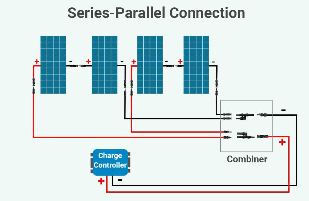
Sizing wires for 4 solar panels wired in series-parallel
In this example, we’ll calculate the size of wires that we need for an 800W solar array. This 800W solar array consists of 4 12V-200W solar panels wired in a series-parallel configuration:
Learn more about series, parallel, and series-parallel connections here.
Let’s also assume that we’re using these 200W Renogy solar panels. Each of these solar panels has the following specs:
- Short-circuit current (Isc): 9.66 Amps
- Optimum Operating Current (Imp): 8.85 Amps
- Optimum Operating Voltage (Vmp): 22.6 Volts
In the image, notice that there are 6 wires that we’ll need to size.
4 of the wires connect the solar panels to the combiner. We’ll refer to these wires as PV source wires.
2 of the wires connect the combiner to the solar charge controller. We’ll refer to these wires as PV output wires.
For the sake of this example, we’ll make the following assumptions:
- The PV source wires are each 8 feet long.
- The PV output wires are each 25 feet long.
- The solar array is going to be ground-mounted.
- The maximum outdoor (ambient) temperature in the area in which the system is installed is 104°F(40°C).
- All the connections and terminals of our equipment are rated for 75°C(167°F) or more.
All of these pieces of information will be necessary to size our wires.
First, let’s start with sizing the PV source wires.
Sizing the wires from the solar panels to the combiner
To size the wires from the solar panels to the combiner, we’ll need to:
- Step 1: make sure the ampacity of the wire is not less than 1.25 times the maximum current.
- Step 2: make sure the ampacity of the wire is still sufficient even at the maximum ambient temperature.
- Step 3: make sure the voltage drop between the solar panels and the combiner does not exceed 1.5%.
Let’s begin with the 1st step.
Step 1: Calculating wire ampacity based on Maximum Current
As explained above, the maximum current is calculated as such:
Maximum Current (Amps) = Short-circuit Current (Amps) x 1.25
Since our PV source wires will each be connected to a string consisting of 2 solar panels in series, the short circuit current going through these wires is going to be equal to the short circuit current of one solar panel (9.66 Amps).
Learn more about solar panel series connection
Therefore, the maximum current going through these wires can be calculated as such:
Maximum Current (Amps) = Short-circuit Current (Amps) x 1.25
Maximum Current (Amps) = 9.66 Amps x 1.25
Maximum Current (Amps) = 12.07 Amps
Now, again, as required by NEC 690.9(B), the ampacity of the wire should not be less than 125% of the maximum current:
Wire Ampacity should not be less than = Maximum Current (Amps) x 1.25
Wire Ampacity should not be less than = 12.07 Amps x 1.25
Wire Ampacity should not be less than = 15.09 Amps
With these calculations, we’ve determined that the ampacity of our PV source wires cannot be less than 15.09 Amps.
Let’s move on to the next step.
Step 2: Adjusting wire ampacity based on ambient temperature
In this step, we’ll need to make sure that the ampacity of our wire is still enough for 15.09 amps even at maximum ambient temperature.
These are the copper wire ampacities for a maximum ambient temperature of 86°F (30°C) from NEC table 310.16, which we’ll need to adjust:
| Copper Wire Size | 60°C(140°F):
Types TW & UF |
75°C(167°F):
Types RHW, THHW, THW, THWN, XHHW, XHWN, USE, ZW |
90°C(194°F):
Types TBS, SA, SIS, FEP, FEPB, MI, PEA, RHH, RHW-2, THHN, THHW, THW-2, THWN-2, USE-2, XHH, XHHW, XHHW-2, XHWN, XHWN-2, XHHN, Z, ZW-2 |
| 16 AWG | – | – | 18 A |
| 14 AWG | 15 A | 20 A | 25 A |
| 12 AWG | 20 A | 25 A | 30 A |
| 10 AWG | 30 A | 35 A | 40 A |
| 8 AWG | 40 A | 50 A | 55 A |
| 6 AWG | 55 A | 65 A | 75 A |
| 4 AWG | 70 A | 85 A | 95 A |
| 3 AWG | 85 A | 100 A | 115 A |
| 2 AWG | 95 A | 115 A | 130 A |
| 1 AWG | 110 A | 130 A | 145 A |
| 1/0 AWG | 125 A | 150 A | 170 A |
| 2/0 AWG | 145 A | 175 A | 195 A |
| 3/0 AWG | 165 A | 200 A | 225 A |
| 4/0 AWG | 195 A | 230 A | 260 A |
Since we’ve checked the temperature ratings of our equipment, and everything proves to be rated for 75°C(167°F) or more, we’ll use the 75°C column of the tables.
According to the 75°C column of the NEC table 310.16, 14 AWG copper wire can handle up to 20 Amps of current.
However, again, the ampacities provided in the table are for ambient temperatures that don’t exceed 86°F/30°C.
In our example, we’ve made the assumption that the temperature in the area can go up to 104°F(40°C). And as mentioned above, the higher the ambient temperature, to lesser the ampacity of the wire.
Now, our solar panels are not mounted on the roof, and our PV source wires are not going to be in a conduit, we only have to adjust the ampacity of our 14 AWG wires for an ambient temperature of 104°F(40°C).
Let’s take a look at NEC Table 310.15 (B) (1) (1):
| Ambient Temperature | 60°C(140°F):
Types TW & UF |
75°C(167°F):
Types RHW, THHW, THW, THWN, XHHW, XHWN, USE, ZW |
90°C(194°F):
Types TBS, SA, SIS, FEP, FEPB, MI, PEA, RHH, RHW-2, THHN, THHW, THW-2, THWN-2, USE-2, XHH, XHHW, XHHW-2, XHWN, XHWN-2, XHHN, Z, ZW-2 |
| 10°C (50°F) or less | 1.29 | 1.2 | 1.15 |
| 11°C (51°F) – 15°C (59°F) | 1.22 | 1.15 | 1.12 |
| 16°C (60°F) – 20°C (68°F) | 1.15 | 1.11 | 1.08 |
| 21°C (69°F) – 25°C (77°F) | 1.08 | 1.05 | 1.04 |
| 26°C (78°F) – 30°C (86°F) | 1 | 1 | 1 |
| 31°C (87°F) – 35°C (95°F) | 91 | 0.94 | 0.96 |
| 36°C (96°F) – 40°C (104°F) | 0.82 | 0.88 | 0.91 |
| 41°C (105°F) – 45°C (113°F) | 0.71 | 0.82 | 0.87 |
| 46°C (114°F) – 50°C (122°F) | 0.58 | 0.75 | 0.82 |
| 51°C (123°F) – 55°C (131°F) | 0.41 | 0.67 | 0.76 |
| 56°C (132°F) – 60°C (140°F) | – | 0.58 | 0.71 |
| 61°C (141°F) – 65°C (149°F) | – | 0.47 | 0.65 |
| 66°C (150°F) – 70°C (158°F) | – | 0.33 | 0.58 |
According to the 75°C column of the table, for ambient temperatures between 36°C (96°F) and 40°C (104°F), the ampacity of our conductor should be corrected by a factor of 0.88.
This means that we’ll need to multiply the ampacity of our 14 AWG wires (@ an ambient temperature of 30°C/86°F) by 0.88 to determine their ampacity at 40°C (104°F):
Wire Ampacity (@ 40°C/104°F) = Wire Ampacity (@ 30°C/86°F) x Temperature Correction Factor
Wire Ampacity (@ 40°C/104°F) = 20 Amps x 0.88
Wire Ampacity (@ 40°C/104°F) = 17.6 Amps
Even at this temperature, our 14 AWG wires will still be able to handle the 15.09 Amps.
So far, we’ve determined that the size of our PV source wires cannot be any smaller than 14 AWG (2.1 mm²). However, we still need to ensure that the voltage drop is less than 1.5%.
This brings us to the 3rd step.
Step 3: limiting the voltage drop across the PV source wires
And use the following table to determine if we need a bigger wire size than 14 AWG:
| Wire size (AWG) | Wire size (Circular Mills) | Wire size (mm²) |
| 14 AWG | 4110 | 2.1 |
| 12 AWG | 6530 | 3.3 |
| 10 AWG | 10380 | 5.3 |
| 8 AWG | 16510 | 8.4 |
| 6 AWG | 26240 | 13.3 |
| 4 AWG | 41740 | 21.1 |
| 3 AWG | 52620 | 26.7 |
| 2 AWG | 66360 | 33.6 |
| 1 AWG | 83690 | 42.4 |
| 1/0 AWG | 105600 | 53.5 |
| 2/0 AWG | 133100 | 67.4 |
| 3/0 AWG | 167800 | 85 |
| 4/0 AWG | 211600 | 107.2 |
So, our 3 variables are:
- Operating Current (Amps): 8.85 Amps.
- One-way wire Length (feet): 8 feet.
- Operating Voltage (Volts): 45.2 Volts (22.6 + 22.6 Volts).
Let’s calculate the required cross-sectional area of our wires (in C.M):
Wire thickness (in Circular Mills) = (12.96 x Operating Current (Amps) x 2 x One-Way Wire Length (feet)) ÷ (0.015 x Operating Voltage (Volts))
Wire thickness (in Circular Mills) = (12.96 x 8.85 Amps x 2 x 8 feet) ÷ (0.015 x 45.2 Volts)
Wire thickness (in Circular Mills) = (1835.136) ÷ (0.678)
Wire thickness (in Circular Mills) = 2706.69 C.M
If you look at the table above, you’ll see that the cross-sectional area of a 14 AWG wire is 4110 C.M, which is more than for what we need (at least 2706.69 C.M). This means that our PV source wires have to be 14 AWG or bigger.
Now that we’ve determined that we’ll be using 14 AWG (copper) cables as our PV source wires, let’s size our PV output wires.
Sizing the wires from the combiner to the solar charge controller
The same process will apply here too, therefore, we’ll follow the same steps as before:
- Step 1: make sure the ampacity of the wire is not less than 1.25 times the maximum current
- Step 2: make sure the ampacity of the wire is still sufficient even at the maximum ambient temperature
- Step 3: make sure the voltage drop between the solar panels and the combiner does not exceed 1.5%
Step 1: Calculating wire ampacity based on Maximum Current
As explained above, the ampacity of the wire cannot be less than 125% of the maximum current going through the wire. The Maximum Current is calculated as such:
Maximum Current (Amps) = Short-circuit Current (Amps) x 1.25
However, the short-circuit current is not that of a single solar panel.
Our 4 solar panels are wired in a series-parallel configuration. Every 2 solar panels are wired in series, forming 2 strings, and the 2 strings are wired in parallel.
When solar strings are wired in parallel, the total current of the solar array is the sum of the currents from the strings.
Learn more about solar panel parallel connection
Since each string has a short-circuit current of 9.66 Amps, and we have 2 strings in parallel, the total short-circuit current is 19.32 Amps (9.66 + 9.66). So, our maximum current is:
Maximum Current (Amps) = Short-circuit Current (Amps) x 1.25
Maximum Current (Amps) = 19.32 Amps x 1.25
Maximum Current (Amps) = 24.15 Amps
The ampacity of the wires that we use between the combiner and the solar charge controller should not be less than 125% of 24.15 Amps:
Wire Ampacity should not be less than = Maximum Current (Amps) x 1.25
Wire Ampacity should not be less than = 24.15 Amps x 1.25
Wire Ampacity should not be less than = 30.18 Amps
Now, we know that the ampacity of our PV output wires cannot be less than 30.18 Amps.
Before we choose the size of our PV output wires, we’ll need to adjust the ampacity based on ambient temperature.
Step 2: Adjusting wire ampacity based on ambient temperature
Here are the ampacities of copper wires at an ambient temperature of 30°C/86°F:
| Copper Wire Size | 60°C(140°F):
Types TW & UF |
75°C(167°F):
Types RHW, THHW, THW, THWN, XHHW, XHWN, USE, ZW |
90°C(194°F):
Types TBS, SA, SIS, FEP, FEPB, MI, PEA, RHH, RHW-2, THHN, THHW, THW-2, THWN-2, USE-2, XHH, XHHW, XHHW-2, XHWN, XHWN-2, XHHN, Z, ZW-2 |
| 16 AWG | – | – | 18 A |
| 14 AWG | 15 A | 20 A | 25 A |
| 12 AWG | 20 A | 25 A | 30 A |
| 10 AWG | 30 A | 35 A | 40 A |
| 8 AWG | 40 A | 50 A | 55 A |
| 6 AWG | 55 A | 65 A | 75 A |
| 4 AWG | 70 A | 85 A | 95 A |
| 3 AWG | 85 A | 100 A | 115 A |
| 2 AWG | 95 A | 115 A | 130 A |
| 1 AWG | 110 A | 130 A | 145 A |
| 1/0 AWG | 125 A | 150 A | 170 A |
| 2/0 AWG | 145 A | 175 A | 195 A |
| 3/0 AWG | 165 A | 200 A | 225 A |
| 4/0 AWG | 195 A | 230 A | 260 A |
According to the 75°C of the table, a 10 AWG wire has an ampacity of 35 Amps, but this ampacity needs to be adjusted.
Now, our PV output wires are going to run through a conduit, however, since there are only going to be 2 wires in the conduit, we don’t need to adjust for conduit fill. Also, since our conduit is not going to be on the roof, we don’t need to use the temperature adder.
Therefore, we only need to adjust the ampacity of our 10 AWG wires for an ambient temperature of 104°F(40°C).
Let’s look at NEC Table 310.15 (B) (1) (1) again:
| Ambient Temperature | 60°C(140°F):
Types TW & UF |
75°C(167°F):
Types RHW, THHW, THW, THWN, XHHW, XHWN, USE, ZW |
90°C(194°F):
Types TBS, SA, SIS, FEP, FEPB, MI, PEA, RHH, RHW-2, THHN, THHW, THW-2, THWN-2, USE-2, XHH, XHHW, XHHW-2, XHWN, XHWN-2, XHHN, Z, ZW-2 |
| 10°C (50°F) or less | 1.29 | 1.2 | 1.15 |
| 11°C (51°F) – 15°C (59°F) | 1.22 | 1.15 | 1.12 |
| 16°C (60°F) – 20°C (68°F) | 1.15 | 1.11 | 1.08 |
| 21°C (69°F) – 25°C (77°F) | 1.08 | 1.05 | 1.04 |
| 26°C (78°F) – 30°C (86°F) | 1 | 1 | 1 |
| 31°C (87°F) – 35°C (95°F) | 91 | 0.94 | 0.96 |
| 36°C (96°F) – 40°C (104°F) | 0.82 | 0.88 | 0.91 |
| 41°C (105°F) – 45°C (113°F) | 0.71 | 0.82 | 0.87 |
| 46°C (114°F) – 50°C (122°F) | 0.58 | 0.75 | 0.82 |
| 51°C (123°F) – 55°C (131°F) | 0.41 | 0.67 | 0.76 |
| 56°C (132°F) – 60°C (140°F) | – | 0.58 | 0.71 |
| 61°C (141°F) – 65°C (149°F) | – | 0.47 | 0.65 |
| 66°C (150°F) – 70°C (158°F) | – | 0.33 | 0.58 |
According to the 75°C of the table, we’ll need to multiply the ampacity of our 10 AWG wires by a factor of 0.88:
Wire Ampacity (@ 40°C/104°F) = Wire Ampacity (@ 30°C/86°F) x Temperature Correction Factor
Wire Ampacity (@ 40°C/104°F) = 35 Amps x 0.88
Wire Ampacity (@ 40°C/104°F) = 30.8 Amps
At an ambient temperature of 40°C/104°F, the ampacity of 10 AWG copper wires is 30.8 amps, which is more than enough for what we need (30.18 Amps).
Until now, we’ve determined that our PV output wires cannot be any smaller than 10 AWG.
Now, let’s see if 10 AWG wires are going to be big enough to limit the voltage drop to 1.5%.
Step 3: limiting the voltage drop across the PV output wires
And use the following table to determine if we need a bigger wire size than 10 AWG:
| Wire size (AWG) | Wire size (Circular Mills) | Wire size (mm²) |
| 14 AWG | 4110 | 2.1 |
| 12 AWG | 6530 | 3.3 |
| 10 AWG | 10380 | 5.3 |
| 8 AWG | 16510 | 8.4 |
| 6 AWG | 26240 | 13.3 |
| 4 AWG | 41740 | 21.1 |
| 3 AWG | 52620 | 26.7 |
| 2 AWG | 66360 | 33.6 |
| 1 AWG | 83690 | 42.4 |
| 1/0 AWG | 105600 | 53.5 |
| 2/0 AWG | 133100 | 67.4 |
| 3/0 AWG | 167800 | 85 |
| 4/0 AWG | 211600 | 107.2 |
So, our 3 variables are:
- Operating Current (Amps): 17.7 Amps (8.85 + 8.85 Amps).
- One-way wire Length (feet): 25 feet.
- Operating Voltage (Volts): 45.2 Volts (22.6 + 22.6 Volts).
Let’s calculate the required cross-sectional area of our wires (in C.M):
Wire thickness (in Circular Mills) = (12.96 x Operating Current (Amps) x 2 x One-Way Wire Length (feet)) ÷ (0.015 x Operating Voltage (Volts))
Wire thickness (in Circular Mills) = (12.96 x 17.7 Amps x 2 x 25 feet) ÷ (0.015 x 45.2 Volts)
Wire thickness (in Circular Mills) = (11469.6) ÷ (0.678)
Wire thickness (in Circular Mills) = 16916.81 C.M
If you look at the table above, you’ll see that the cross-sectional area of a 10 AWG wire is only 10380 C.M, which is too small for what we need (at least 16916.81 C.M). Even 8 AWG wire will not be sufficient.
This means that our PV output wires have to be 6 AWG or bigger,

My panels don’t list “Operating Voltage.” They list Rated Voltage, Open-Circuit Voltage and Max. System Voltage. Which one do I use in the formula to limit voltage drop?
Hello Lilly,
Use the Rated Voltage specification.
The Open-Circuit Voltage represents the voltage of the solar panel when the circuit is open and the panel is under sunlight.
The Max. System Voltage (I’m guessing it says 600 Volts) represents the maximum voltage of the string that shouldn’t be exceeded when these solar panels are in series.
The Rated Voltage spec represents the voltage of the panel at the maximum power point.
Hope this helps.