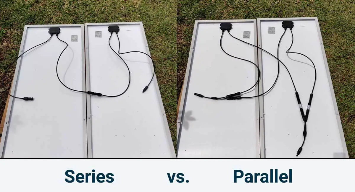
In this tutorial, I’ll show you how to wire solar panels in series and how to wire them in parallel.
Once we’ve got that covered, I’ll also explain the difference between these two configurations in Voltage (Volts) and Current (Amps) and provide a real-life example.
Finally, I’ll discuss the pros and cons of each configuration to help you figure out which one fits your needs best.
Let’s dive in.
I get commissions for purchases made through links in this post.
How to wire solar panels in series and in parallel?
Every solar panel typically comes with a female and a male MC4 connector. Usually, the female MC4 connector stands for the negative terminal, and the male MC4 connector represents the positive terminal of the solar panel. However, keep in mind that this standard isn’t always consistent.
Regardless, the first crucial step before making any connections is identifying the positive and negative wires of your solar panels.
You can usually find polarity indicators somewhere on the solar panel itself. Look for a “+” sign, which indicates the positive wire, and a “-” sign for the negative wire.
These polarity markers can be located on the junction box, the wires, or the MC4 connectors.
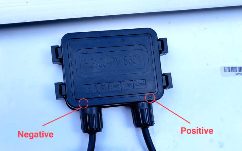
If the manufacturer hasn’t clearly labeled the polarity of the solar panel, another approach is to use a multimeter to measure voltage.
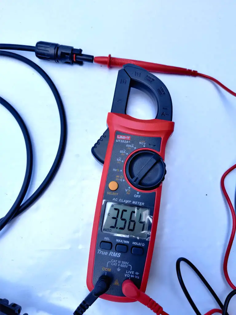
To do this, insert one multimeter probe into each of the MC4 terminals.
If the reading shows a positive voltage value, it means the positive (red) probe is connected to the positive end of the solar panel. If the voltage value is negative, then the red probe is connected to the negative end of the panel.
For instance, in the image above, you can observe the red probe inserted into the male MC4 connector of the solar panel, signifying the positive terminal. As a result, my multimeter displays a positive voltage reading.
After identifying the positive and negative wires of your solar panels, be sure to mark them before proceeding.
Now, let’s kick off with the series configuration.
How to wire solar panels in series?
To wire your solar panels in series, simply link the positive MC4 connector of the first solar panel to the negative MC4 connector of the next one, and continue this pattern for the remaining panels.
Once you’re finished, you’ll have two unconnected terminals at each end of your series—a positive and a negative. These can be connected to the solar charge controller using extension cables.
The great thing about connecting solar panels in series is that you won’t need any extra components; all you require are your solar panels and a pair of extension cables to link the solar string to the solar charge controller.
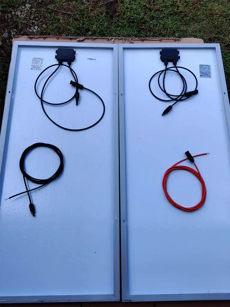
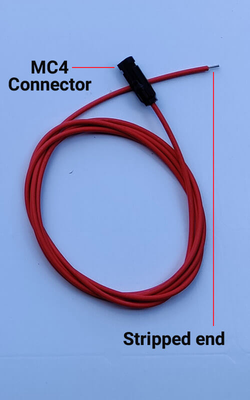
Each of these extension cables comes with an MC4 connector on one end, which attaches to the solar panels, and a stripped end that connects to one of the terminals on the solar charge controller.
As an illustration, for this tutorial, I’ve connected the positive MC4 connector of the left panel to the negative MC4 connector of the right panel since I’m working with only two solar panels.
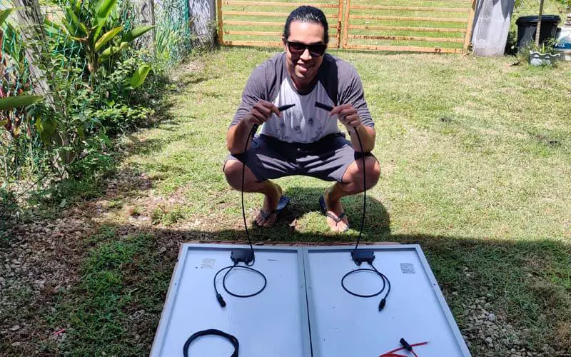
And voila! we have a string of 2 solar panels:
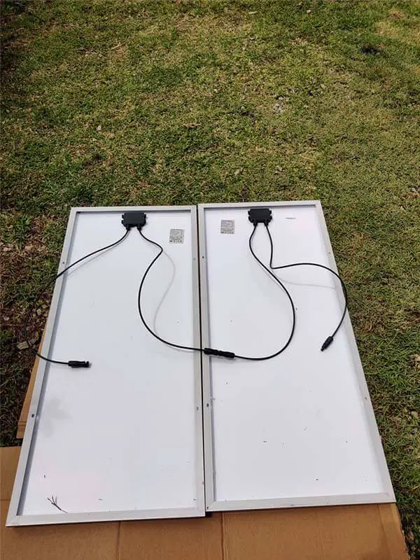
To hook up the solar panels to the solar charge controller, I simply used the extension cables. I connected the negative end of the string (on the left) to the negative terminal of the SCC and linked the positive end of the string (on the right) to the positive terminal of the charge controller.
How to wire solar panels in parallel?
To wire solar panels in parallel, you’ll require a couple of branch connectors. These connectors link all the positive terminals of the solar panels, creating the positive terminal of the solar array, and they connect all the negative terminals to form the negative terminal of the solar array.
In addition to your solar panels and extension cables, you’ll need two extra components:
- A pair of MC4 Y branch connectors.
- MC4 inline fuses, if necessary.
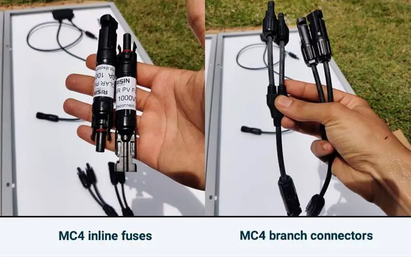
In the image above, you can see a pair of 2-to-1 (or Y) MC4 branch connectors, since I’m only connecting two solar panels in parallel. However, if you have more solar panels, you’ll require branch connectors with a matching number of inputs.
For instance, if you have three solar panels, you’ll need a pair of 3-to-1 MC4 branch connectors. To wire four solar panels in parallel, use a pair of 4-to-1 MC4 branch connectors.
Now, to wire my two solar panels in parallel, the initial step was connecting the fuses to the positive leads of the solar panels.
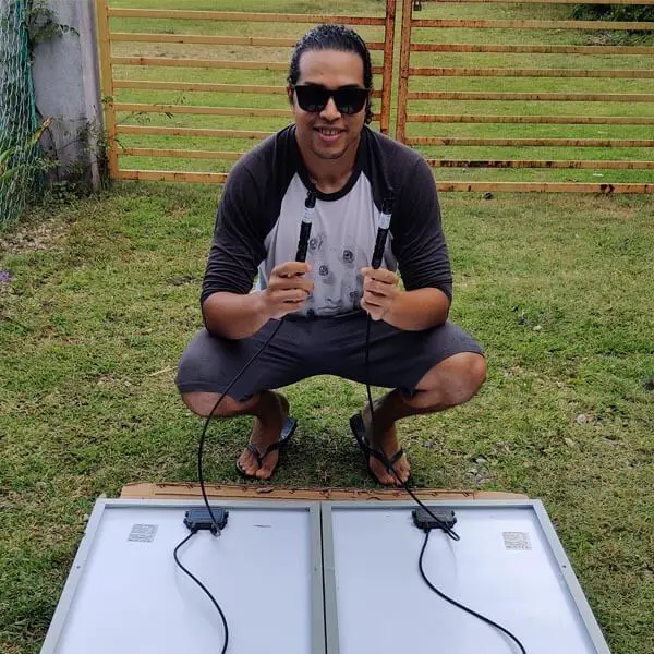
Read more about fusing solar panels.
After fusing the solar panels, I joined the positive wires using a Female-Female-Male MC4 branch connector and connected the negative wires using a Male-Male-Female MC4 branch connector.
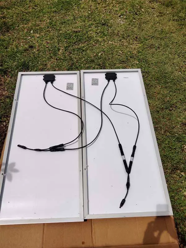
The wire on the left represents the negative end of the solar array. Using the extension cables, it should be connected to the negative PV terminal of the solar charge controller. The wire on the right is the positive wire, which needs to be connected to the positive PV terminal of the charge controller.
Solar Panels Series vs Parallel: What Is The Difference?
Whether you connect solar panels in series or in parallel, the total power output (in Watts) is the sum of the power generated by each solar panel. The difference between these two types of configurations is the total Voltage (Volts) and the total Current (Amps) of the solar array.
When you wire solar panels in series, you raise the Voltage of the system, while the Current stays the same.
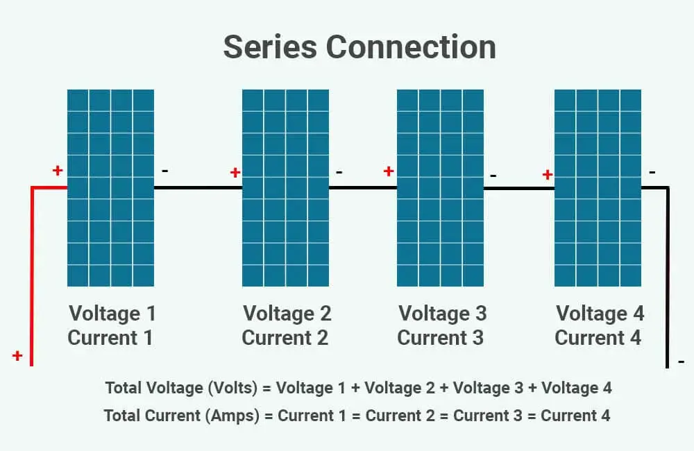
Voltage:
Total Voltage (Volts) = Voltage 1 + Voltage 2 + Voltage 3 + Voltage 4
Total Voc (Open-Circuit Voltage) = Voc 1 + Voc 2 + Voc 3 + Voc 4
Total Vmp (Maximum Power Voltage) = Vmp 1 + Vmp 2 + Vmp 3 + Vmp 4
Current:
Total Current (Amps) = Current 1 = Current 2 = Current 3 = Current 4
Total Isc (Short-Circuit Current) = Isc 1 = Isc 2 = Isc 3 = Isc 4
Total Imp (Maximum Power Current) = Imp 1 = Imp 2 = Imp 3 = Imp 4
When you wire solar panels in parallel, you raise the Current of the system, while the Voltage stays the same.
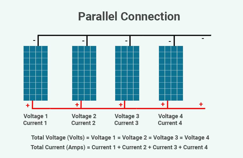
Voltage:
Total Voltage (Volts) = Voltage 1 = Voltage 2 = Voltage 3 = Voltage 4
Total Voc (Open-Circuit Voltage) = Voc 1 = Voc 2 = Voc 3 = Voc 4
Total Vmp (Maximum Power Voltage) = Vmp 1 = Vmp 2 = Vmp 3 = Vmp 4
Current:
Total Current (Amps) = Current 1 + Current 2 + Current 3 + Current 4
Total Isc (Short-Circuit Current) = Isc 1 + Isc 2 + Isc 3 + Isc 4
Total Imp (Maximum Power Current) = Imp 1 + Imp 2 + Imp 3 + Imp 4
As an illustration, I’ll connect two identical 100W solar panels both in series and in parallel, and demonstrate the resulting voltage and current.
Here are the electrical specifications for each of these solar panels:
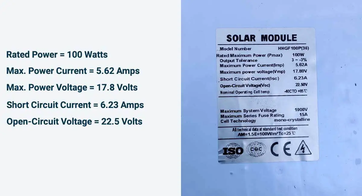
Let’s start with a series connection.
Solar panels in series:
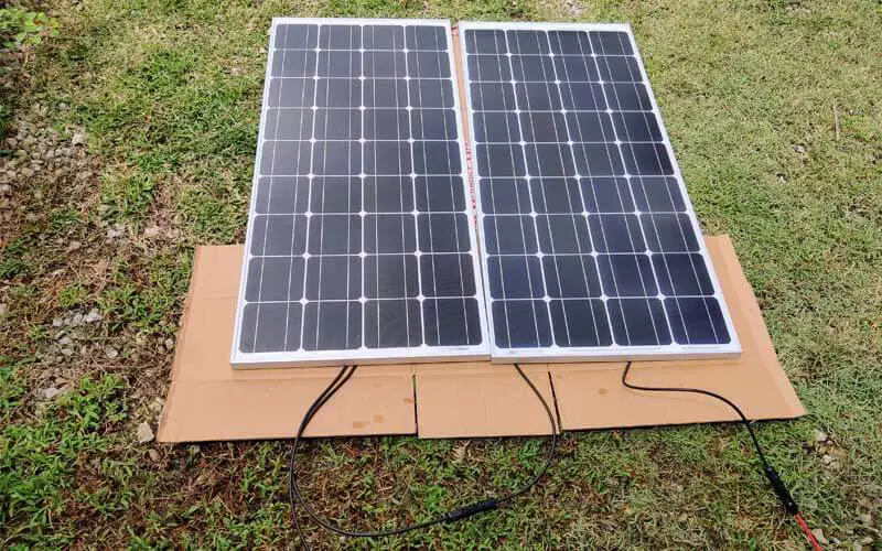
As previously explained, in a series connection, Voltage increases while Current remains the same. Therefore, with these series-connected solar panels, we now have a solar string with the following specifications:
- Rated Power = 100 Watts + 100 Watts = 200 Watts
- Max. Power Current = 5.62 Amps
- Max. Power Voltage = 17.8 Volts + 17.8 Volts = 35.6 Volts
- Short Circuit Current = 6.23 Amps
- Open-Circuit Voltage = 22.5 Volts + 22.5 Volts = 45 Volts
However, the actual Voltage and Current that the string produces at a given moment will depend on the amount of sunlight available for the solar panels to convert into electricity and the type of solar charge controller you’re using.
In my case, I’m using an EPEVER MPPT charge controller. But as you can see in the image above, it was cloudy, and the solar panels were not receiving direct sunlight.
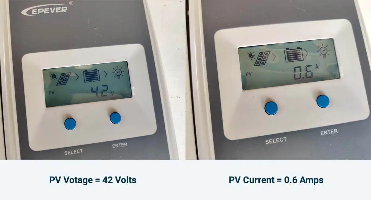
As a result, the string was only generating approximately 25 Watts of power instead of the full 200 Watts:
Power (Watts) = Voltage (Volts) x Current (Amps)
Power (Watts) = 42 Volts x 0.6 Amps
Power (Watts) = 25.2 Watts
Now, let’s explore how voltage and current differ in a parallel connection.
Solar panels in parallel:
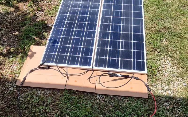
As previously mentioned, in a parallel connection, the Current increases while the Voltage stays the same. With this setup, we now have a solar array with the following specifications:
- Rated Power = 100 Watts + 100 Watts = 200 Watts
- Max. Power Current = 5.62 Amps + 5.62 Amps = 11.24 Amps
- Max. Power Voltage = 17.8 Volts
- Short Circuit Current = 6.23 Amps + 6.23 Amps = 12.64 Amps
- Open-Circuit Voltage = 22.5 Volts
In this second test, the solar panels received more sunlight, although it still wasn’t optimal:
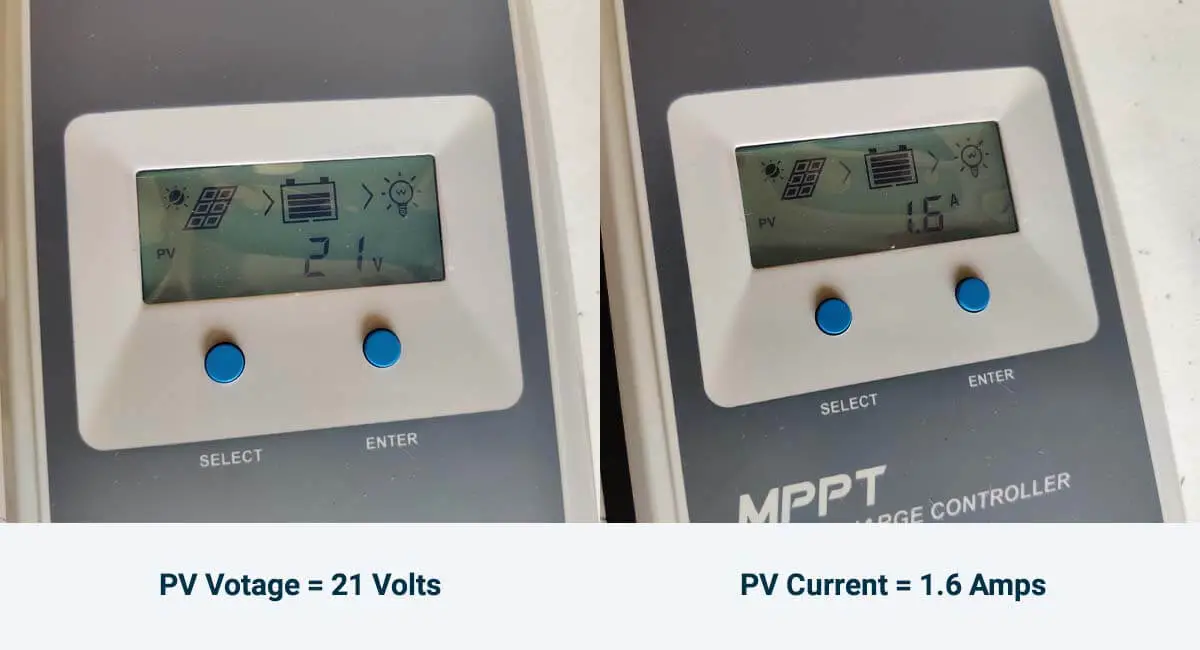
At 21 Volts, our parallel-connected solar panels were producing only 1.6 Amps, which amounts to 33.6 Watts:
Power (Watts) = Voltage (Volts) x Current (Amps)
Power (Watts) = 21 Volts x 1.6 Amps
Power (Watts) = 33.6 Watts
While the parallel connection in my test seems to yield more power, this is because the solar panels received a bit more sunlight. It’s important to note that a parallel configuration doesn’t always result in more power.
Each configuration has its own set of pros and cons, and your choice between them will depend on the specific requirements and limitations of your solar system.
Let me explain.
Solar Panels Series vs Parallel: Pros and Cons
Connecting solar panels in series:
Pros:
- Simplicity and Cost: It’s easier and more cost-effective to connect solar panels in series. No additional parts are needed, which simplifies the arrangement and lowers expenses.
- Reduced Current: Series connections mean less current flowing through the wires, allowing for the use of thinner and more affordable wires, and eliminating the need for fuses.
Cons:
- Charge Controller Requirement: When you wire solar panels in series, you’ll often need to use an MPPT solar charge controller. Using a PWM charge controller can make the solar panels susceptible to shading and mixed lighting conditions.
- Cost: MPPT charge controllers are a better technology and are typically recommended for higher system efficiency, but they are more expensive. This may not always be cost-effective, especially for small solar systems.
So, when to opt for a series configuration?
1- If you’re using an MPPT solar charge controller:
MPPT (Maximum Power Point Tracking) charge controllers have a valuable capability: they can decrease the voltage from the solar array while simultaneously increasing current at their output by the same ratio. This allows you to maintain a series configuration with a higher voltage without sacrificing power.
MPPT charge controllers also enable you to wire your solar panels in series because they can activate the bypass diodes within the solar panels if one of the panels receives less sunlight than the others, such as in cases of partial shading or mixed lighting conditions.
Learn more about solar panel shading.
Just be cautious to ensure that the maximum voltage from your solar array doesn’t exceed the input voltage tolerance of your MPPT charge controller.
Related: Make use of our MPPT calculator.
2- If you have mixed solar panels with similar amperage ratings:
When you have solar panels from different manufacturers with varying voltage and amperage ratings, it’s important to consider the implications:
As previously explained, in a series connection, the voltages from the panels add up while the current remains the same. With mixed solar panels, if the voltage and amperage ratings are not identical, the voltages still add up, but the current will be equal to the lowest current rating in the string.
However, if you have mixed solar panels with different voltage ratings but relatively close current ratings, it can still make sense to wire them in series. This can help you make the most of the available power output while managing variations in voltage ratings.
3- If you have long wire runs:
When determining the wire size between the solar panels and the charge controller, two key factors come into play:
- Current Load: The amount of current flowing through the wire. Higher current requires thicker wires to handle the load.
- Voltage Drop: The distance between the solar panels and the solar charge controller impacts the wire thickness required to mitigate voltage losses.
Wiring your solar panels in series allows for the use of smaller gauge wires. This is because the current is relatively low, and the higher system voltage can tolerate a higher voltage drop compared to a lower system voltage.
Connecting solar panels in parallel:
Pros:
- Cost-Efficiency: Wiring solar panels in parallel allows you to use PWM charge controllers, which are more budget-friendly compared to MPPT charge controllers.
- Individual Panel Performance: In a parallel connection, each panel operates independently in terms of current production. If one panel is shaded or receives less sunlight, it doesn’t affect the current production of the other panels.
Cons:
- Higher System Current, Lower Voltage: Parallel wiring leads to higher system current and lower system voltage, necessitating thicker wires to handle the current and limit voltage drop.
- Additional Components: A parallel configuration requires the use of extra components like branch connectors and fuses, which are almost always necessary when wiring solar panels in parallel.
So, when to opt for a parallel configuration?
1- If you’re using a PWM charge controller:
When using a PWM charge controller, you’ll need to make sure that the nominal voltage of the solar array matches that of the battery. For example, if you have two 12V solar panels charging a 12V battery with a PWM, these solar panels would have to be wired in parallel to minimize energy losses.
2- If you have partial shading and variable lighting conditions:
When solar panels are exposed to varying amounts of sunlight due to partial shading or facing different directions, parallel wiring reduces system losses.
Each solar panel operates independently, meaning one panel’s reduced output doesn’t impact the output of the others.
2- If you have mixed solar panels with similar voltage ratings:
When dealing with mixed solar panels that share the same nominal voltage (e.g., 12V) but have different current ratings, you can still wire them in parallel.
The total current of the array will be the sum of the currents from each panel, and the voltage of the array will match the lowest voltage rating in the array.



You talk about panel output, volts & amps. My question is about the voc voltage, how does that change in series & parallel circuits?
Hey there Roger,
You’ll find the answer to your question in the article.
whats the best way to wire solar so you can get the maximum out put . i read that in series if the cloud comes over and blocks the first panel you have stuff all power it seems more like every cell has a tap and water flows through all the panels and if a tap is turned off then no water flows to the rest restricting out put . in parallel the out put is not to restricted ? .so is a series parallel system the best way to wire panels or does voltage output come into it and what is the minimum voltage the control unit need
Hey there Richard,
Please read my article on the effects of shading on solar panels (series vs parallel), I’m sure you’ll find all the info you need there.
Hope this helps.
Hi
I have a canal boat with six x 350wat solar panels, and four 12v 300amp lithium batteries. These are connected in a 24v circuit. My BMS shows a 28.40v for all four batteries, but the capacity has gone down from 100% to 35% in the last few weeks with very little use. How can this be with fully charged batteries ?.
Kind regards Alan
Hey there Alan,
Please define “very little use”?
If, in the last few weeks, your solar panels have been getting suboptimal sunlight, and your batteries are sized just enough to offset your daily energy consumption, this seems normal.
So, how much energy (in Watt-hours or kiloWatt-hours) do you usually use on a daily basis?
Also, how many Peak Sun Hours do you get?
What happens if 2 panels are connected in series and then connected to one panel in parallel? All panels have the same specs.
Hello there,
In such a case, the single solar panel will likely be act as a short-circuit due to its bypass diodes. If an MPPT is used, the bypass diodes will not work, and the single panel will end up lowering the combined voltage of the other two panels, which means you’ll have the same power output as if you only had 2 panels in parallel.
This is not advised.
Hope this helps.
Hi
I just purchased an Anker SOLIX F2000 Solar Generator with a 400w portable solar panel. The specs show the following:
Open Circuit Voltage 48.5V
Power Voltage (Vmp) 39V
Power Current (Imp) 10.25A
I want to put 3 additional panels I already have (Unisolar Model Type US-64) in series together, then in parallel with the Anker panels. The specs I have on this are:
Open Circuit Voltage 23.8V
Voltage Max Power 16.5V
Current Max Power 3.88
Max Power 64W
Is this a workable way to maximize my input to the solar generator?
What numbers could I reasonably expect?
Any advice?
Thanks so much for your input- I appreciate it.
Tim
Hi tim, after running the numbers I suggest you wire the 3 identical solar panels in parallel, and then wire that array in series with you 400W solar panel.
The setup you suggest would also work but you would end up losing about 40 Watts. The 2nd configuration will minimize those losses to about 23 Watts.
I hope this helps.
Hi Younes,
Thanks for your response- it demonstrates why you’re the engineer and I’m not! So doing as you suggest, what would you estimate my Power Voltage (Vmp) and Power Current (Imp) to be, and would you anticipate any issues with a 60V max input to my Anker SOLIX F2000 Solar Generator?
I have a partially shaded lot at certain hours. I have 4 400 watt panels for my Ecoflow delta pro. Should I wire in series due to the shading?
Hello Julian,
Well, the Ecoflow Delta PRO has a built-in MPPT charge controller. So, in the case of partial shading, the MPPT should be able to activate the bypass diodes inside your solar panels. So to answer your question, Yes, a series connection is probably the right move.
Hi Tim
I got two panels of 400 watts having capacity of 40 volts and 10 amperes while got three panels of 575 watts having capacity of 42.6 volts and 13.5 amperes.
Kindly advise how I can get max output. I got mppt controller that can operate even at 30 volts.
I believe the most obvious solution here is to wire everything in parallel, so you’ll end up with an array of 5 solar panels in parallel. With this configuration you’ll only lose about 100 Watts of power. But this means you’ll need thicker wires between the junction and the charge controller…
I have a 40A MPPT controller. I am about to buy a 525W panel for an area that will be shaded. I’m wondering if I should use one panel or multiple panels in an what array for best results?
It really depends on the shading situation. A single solar panel will have bypass diodes so if it’s partially shaded vertically, the bypass diodes should be able to disconnect the shaded area, This is assuming the bypass diodes are operational.
But if it’s partially shaded horizontally, it would be similar to being completely shaded. Of course, if it’s completely shaded in the first place, that bad.
In general, it is better to used multiple solar panels wired in parallel, and place them in a way that if it’s partial shading, it would only hit some of the panels.
Again this depends on the situation.
Hope this helps.
Hi,
I forget one thing which I didn’t mention that I use water cooler directly on 1 panel without mptt last 5 years now want to add 2 more panel and 1 more cooler series or parallel is best thanks
Hi,
I read ur article but I didn’t understand which Is good series or parallel I have 1 panal & I,m using without mppt last 5 years now I Purchased 2 more panel plz tell me shortly which is best series or parallel without mptt thanks for early reply
Parallel is probably better for you.
Hello,
Great article, But I am a little confused. I have Ecoflow Ultra, with 6-100 watt panels. I was thinking on making 2 sets of 3 in parallel. That is 3 in series, hooked up in parallel to another 3 in series. Is that a correct way of doing it?
Hey Tim,
Sounds right, just double check that the setup is compatible with the input ratings of the EF. The max input voltage on the Ecoflow must be higher than the open-circuit voltage of the solar array (Voc of one panel times 3 in your case).
good morning, i read all i could online just finished up a larger battery backup for my home in tn, i have 2 310 watt panels in series 2 300 AH lipo batteries a 3500 watt 24 volt inverter and a epever 50 A 150 volt charge controller, my question is if i run a coulple of freezers just to get a feel of how long i can run them two full days and nights i dont think i have enough panels to recharge fast in a day or so still waiting as of today i bought 6 395 watt bi facial i was planning on mounting on a ground frame in full sun my question is when i run the solar wire to my house is there a way to have another switch where i can run the new 6 panel in low light or faster charge and then run my current switch or in winter months run both strings i just can figure this out thank you for your help
Hello,
I dont know the size of those freezers, if “couple” means 2 or 3 here, and the voltage of those batteries, but I believe those batteries would be enough to run the freezers for 48 hours. The 2 310 Watt panels alone are definitely not enough to recharge the batteries fast enough though.
I’m not sure about your 2nd question, can you be clearer please. Not sure what your objective is.
I have (6) 250 w 25v solar panels, with (2) 12v 300ah batteries in series. the batteries do not charge and discharge equally. Do you have any ideas of what’s wrong? This shuts down the system and I have to recharge the batteries back full.
I purchased an Anker Solix f3800 with 2 405w panels. I was looking to simply power my refrigerator. After 6 weeks of emailing with AS customer service and getting no where I am hoping you can assist me. connecting each panel independantly. (Houston, TX, panels due south at a 20 deg angle, no obstructions) each panel produces 280-290 watts.(per the monitor on the f3800) When connected in parallel the wattage maxes out at 400w. I have run my tests with anker’s 10ft cables their mc4 – xt60 adaptor. Also run with 50ft 10awg cables with the same results. I am pretty sure it is not the cables as Anker seems to think. My guess is either the panels are over amping ot the controller in the 3800 is limiting. I have just headed into the third round of a circular email conversation with anker Customer service. I can send the specs it that helps. Thanks
Hey there,
From what I understand, this model has a limit on input current, for input voltages between 11 and 32 it will only allow up to 10 Amps of input, and for 32 to 60 volts up to 25 Amps.
I think your panels have an operating voltage of 31.18 Volts. So with 2 of these panels in parallel, you’re still producing less than 32 Volts, and therefore limited to 10 Amps.
Thanks for your response. i can’t think of anything to improve what I have.
Series is too much voltage so I guess I’ll just have to scratch my head and wonder why anker would package these together. With what is known of the f3800, Is there a brand of fixed panels that would maximize the 1200w input on the 3800? Again I am grateful for your willingness to share your knowledge.
You’re welcome!
And yes, I don’t really understand why they’d design their inputs like that.
A solar panel that comes the mind is the LG NeON 2, these panels have a Vmp of 41 Volts. If you parallel 3 of these panels you should max the unit out.
You can also try to get like 6 12V-200W solar panels from Renogy. These panels are rated at 19.2 Volts for their Vmp, so if you connect them in a 2S3P configuration, they should max out the f3800.
Hope this helps.
Sorry about the double post. I checked the spec sheet on the 3800 and with the current firmware, 2.1.1, its 11-28v = 10amp. 28-60v = 27A max I get 35 v from each panel testing with a multimeter. I was wondering this morning if I couldn’t hook an additional panel or 2 (required specs unknown) in series with one of the 405w and connect that to the 3800. Would that boost the voltage enough to allow the 25 amp input? I’m just trying to make lemonade here.
That might work, just make sure amperage of those panels is close to that of the 405W panels.
Hi, I lost a solar panel during recent hurricane and wondered if I can continue to use the remaining 3 panels in the string while I search for a replacement panel. My system is normally 3 strings of 4 panels each wired in series. I’m presently operating the system only 2 strings of 4 panels and everything seems to be working fine. Just taking a little longer to charge the batteries each day with reduced number of panels. So, in the interim, the system would be 2 strings of 4 panels and 1 string of 3 panels. A second question is a new replacement panel is a little lower open circuit voltage, 48.88 vs 45.80 in the one string. Will this work OK knowing from your article that the voltage for that string will be lower overall than the other two strings. The solar company does not make the exact panel any longer. Thank you
Hey there Robert, I’m sorry to hear that.
With one less panel your setup now operates at a PV voltage of 3 panels instead of that of 4 panels, so even though you have 11 panels left your PV array is practically a 9 panel array now, that’s a 25% loss in power production.
Even if the new panel you’re looking at has less voltage, it would still be a good idea to add it to that 3rd string to increase the voltage of the array and get it closer to what it was. This would reduce your losses to about 1-2% instead of 25%.
Thank you Younes for such a quick reply, I’m not sure I’m quite understanding why a 25% loss. It seems with two good strings operating out of three the loss would only be as high as 33%. So, with 3 good panels operating on the third string, the loss would be quite a bit less that 25%. By your example in the article, I would add the voltage up as follows…. 48.88 x 4= 195V for each of the two good strings and 48.88 x 3= 146.6V for the diminished string. All three strings go to a electrical combiner box at the array and are all added together in one set of conductors to the inverter and batteries, therefore it seems all the panels are still adding to the total and the loss would be less than 25%. Would it be possibly for you to show us how your calculations went to get to the 25% loss? Thanks so much!
The 25% loss is due to the fact that the voltage of the array is equal to lowest string voltage, which means that your whole array is operating at the voltage of 3 panels rather than 4 panels (3/4=75%). This is of course assuming you have 3 parallel strings, 2 with 4 panels and 1 with 3 panels, that are all connected to the same input at the inverter.
For example, let’s say the operating voltage of 1 single panel is around 37 Volts (Vmp), and its operating current at full sunlight is 10 amps (Imp). So, under full sunlight, each string should be producing around 148 Volts (37×4), and 10 Amps. Since you normally have 3 of these strings, the whole array should be producing 148 Volts, and 30 Amps (10×3). In Watts that’s 4440 Watts under good conditions (148 x 30).
However, since one panel is missing, the voltage of the array will be brought down to the lowest string voltage, which is now around 111 Volts (37*3). The current will remain the same at around 30 Amps (it will actually be slightly higher if you look at the I-V characteristic).
So now, the array is producing 3330 Watts (111 x 30). That’s a 1110 Watt loss (4440 – 3330), which represents 25% of the power you should be producing under good conditions (1110 ÷ 4440).
If you have any more questions, would be happy to help.
Wow! So, calculating the difference in wattage between just leaving the two full strings on-line for now (and third string off-line) until I get a replacement vs. putting the third string back on-line with only three panels, thereby reducing the voltage across all strings….really not a big difference in total wattage between the two scenarios. Three partial strings of 3 panels each is 4,790 watts vs. two full strings of 4 panels is 4,258 watts. A difference of only 532 watts. The whole array would be 6,388 watts with all panels on-line. With such a small amount I might just leave the third string off-line until a can source a replacement panel. Especially since the weather is milder and load requirement is less. My panels are 48.88 volts each and 10.89 open circuit amps. Do my numbers seem accurate and would you have the same thought process on leaving the third string off-line for now? I don’t like taking too much of your time. Do you have an LLC where someone can get more in-depth consultation for your time in exchange for payment? I do have plans to add additional renewable power sources and could use some insights. Thank you Younes!
When calculating potential power production, use Vmp (max power) and Imp (max power) instead of Voc (open circuit) and Isc (short-circuit).
I would just leave the 3rd string connected, as it still helps you produce more power and wouldn’t do any harm. So yeah, why not just leave it there?
As for your question, I do consultation, but it depends on what you plan on doing and what information you would need, just to make sure it is within my scope to answer your questions. You can contact me at [email protected].
IM a retired Navy Electronics tech 76 years old. I assembled 12 100w 1200W and solar panels in parallel (michigan lots of trees and weather) IM using a 60w MPPT/PWM ooycyoo Controller and 3 Everstart 12v 109ah DC27 deep cycle batteries. Wiring is 2AWG across the board with a 3000w pure sine wave inverter at 85% eff. Tested all batteries with electronic battery tester and bat Load tester OK. IM running shutoff at 12vdc, Fully charged batteries, hooked up (16a 120v 325w christmas lights at inverter output) for 2 hours before inverter turns off (should run 3x that right!) after shut down battery voltage comes back up to at least 12.5v at rest. Checked everything 3x one item at a time can’t find proble. Any idea? Patrick
Hello Patrick,
From what I understand, your batteries are wired in parallel, and my initial thought was the 2AWG battery wires might be too small for the 3000W inverter, which would cause a voltage drop if the 3000W inverter was maxed out. But if your load is only 325 Watts max, the 2 AWG should be fine.
Are your batteries new? if they have been sitting there for long their capacity might have lowered due to sulfation. If that’s the case, your only option would be to just lower the shutoff to like 11.75 Volts if you can and see how long of a runtime that gets you.
Tell me what you think.
Hello, I am wondering what mppt charge controller would work if i had the new Renogy 200w Shadowflux(1) and a Shadowflux 120 panel(1) in series. I am using a lead acid Optima(ds) battery. I plan to have a 2000 watt inverter for occasional use.
Is this the best controller type for me? Should I connect in parallel with a different controller?
give me a couple suggestions, if you can.
Hello,
Looking at the specs of those solar panels, I believe it is better to wire them in parallel, as the current ratings are way too different.
When you do wire them in parallel, the voltage of the array will be equal to the lower of the 2 voltages, which in this case is that of the 120W panel (28.89 Vmp and 33.69 Voc).
MPPT charge controllers that would be good for this setup can be rated 20 Amps like these controllers:
– The victron 100V/20A MPPT.
– The Renogy 100V/20A MPPT.
But if you want some room for expansion, use 30 Amp controllers. such as:
– The victron 100V/30A MPPT.
– The EPEVER 100V/30A MPPT.
Hi Younes, I am thinking of purchasing two identical 195W panels to add to my existing panel on my RV. It currently has a PWM controller but I will replace it with a MPPT. I am not sure of the power rating of my existing panel, but it is quite old. Given that the RV is obviously a 12V system, please consider the following scenarios:
1) if the existing panel is close to 195W, should I wire the system in series or parallel?
2) if the existing panel is a lower power rating (say, 100W or so), should I wire the system in series or parallel?
I also have a 200Ah LiOn battery in the system as well as a 3,000W inverter/charger
thanks
Since the old panel is likely a 12V one, if the new 195W panel is rated at 12V nominal, wire them in parallel, if its rated at 24V nominal, wire them in series.
It would have been more helpful if you got the specs of the panels. If you can’t see the specs of older panel, maybe look at the stats that the PWM displays if it does have a display, this will give you a good idea about the panel specs.
Just remember, when you wire in series, same current, added voltage, but string takes on the lowest current produced by the weakest panel in the string. When you wire in parallel, same voltage, added current, but the array takes on the lowest voltage produced by the weakest panel in the array.
Thank you Younes, I have a Ph.D. in aerospace engineering, so I understand series vs. parallel 🙂
All panels are 12V. My gut feel was to wire them in parallel. The new panels are 195W, Voc 24.5 and Isc 10.14. The old one is a GoPower from around 2006 so maybe somewhere between 100W and 160W, not sure. It currently uses a PWM 30A controller, but the panel doesn’t really have much oomph.
So I agree that parallel is likely the correct connection type, given that they are all 12V panels, but the original panel may be much lower power. Your final comment is why I chose that configuration, so I was basically looking for confirmation from a solar expert 🙂