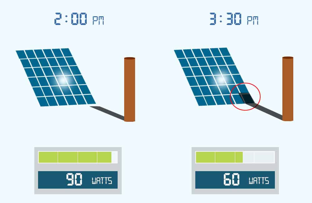
In general, solar panels can work in the shade, but the effects that shade has on solar panels might be different than what you would expect.
For example, in the image above, you can see that one shaded cell (out of 36 cells) can have an enormous impact on power production. This might seem strange but it is true.
If you read this article, you’ll have a complete understanding of solar panel shading, its effect, and solutions.
In this article, I will talk about the relation between solar power production and sunlight conditions, the effect of shading on a solar panel, a string of panels, and on multiples string of solar panels. And then I will discuss a few ways to mitigate these effects.
Do solar panels work in the shade?
Solar panels are not meant to operate in the shade, they are actually tested under optimal lighting conditions (1000W/m²). But should it be unavoidable, do solar panels work in the shade?
If a solar panel is completely under shade, the current it generates will be very low, which means low energy production. If the solar panel is only partially shaded, depending on which cells are shaded and if the solar panel has working bypass diodes, it might still work.
The amount of power a solar cell produces depends directly on how much sunlight it is receiving, this amount of sunlight is referred to as Solar Irradiance and is measured in W/m² (Watts per Square Meter).
When a manufacturer makes a solar panel and gives it a power rating (200 Watts for example), this rating is given to the solar panel under certain conditions, these conditions are called Standard Test Conditions or STC for short.
For example, the standard test condition for solar irradiance is 1000W/m². This means that a 200W solar panel can only produce 200 watts if it’s receiving 1000W/m² of solar irradiance.
Related: How much power does a 200w solar panel produce?
For example, consider a 100W solar panel, with the following specifications:
- Rated Power: 100 Watts
- Rated Current: 5.86 Amps
- Rated Voltage: 17.1 Volts
The following table shows what the power production would look like for the solar panel under different amounts of solar irradiance:
| Solar Irradiance | 200W/m² | 400W/m² | 600W/m² | 800W/m² | 1000W/m² |
| Output Current (Impp) | 1.18 A | 2.34 A | 3.52 A | 4.68 A | 5.86 A |
| Output Voltage (Vmpp) | 15.7 V | 16.1 V | 16.5 V | 16.9 V | 17.1 V |
| Output Power (Pmax) | 18.5 W | 38 W | 58 W | 79 W | 100 W |
When a solar panel is equally shaded, the amount of light it is receiving is very low. This does not always reflect on its voltage, but it directly affects the current. And since power is the product of voltage and current (Power = Voltage x Current), the power production is going to be mediocre.
Okay, so don’t put solar panels under shade, right?
But what if only a portion of the solar panel is shaded, say… one or a few cells?
The next sections explain how a solar panel reacts to different conditions of shading.
Effects of shading on a single solar cell
A solar panel is made of individual solar cells, which are generally all connected in series (positive of cell connected to the negative of the next cell and so on).
The standard individual solar cell produces around 0.2 Amps per square inch (about 0.03 Amps per square centimeter) and about 0.5 Volts.
When it is shaded, the amount of current a solar cell produces is proportional to the unshaded area. As long as it’s not completely blocked from light, the voltage of a solar cell doesn’t really react to shading.
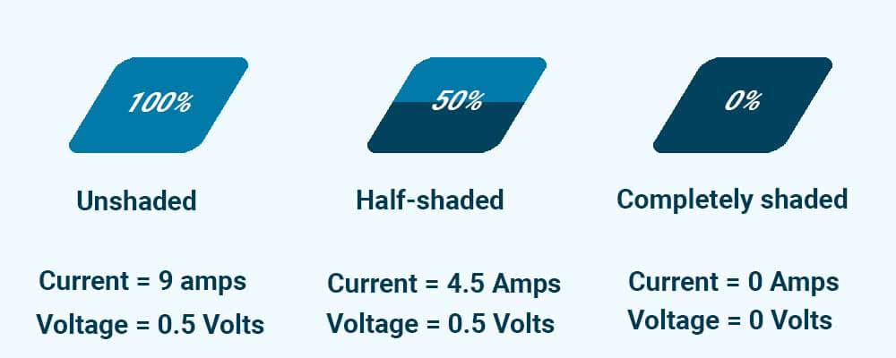
As you can see in the image above, when 50% of the cell is blocked from sunlight, its current is cut in half. Its voltage on the other hand stays the same.
When it’s completely blocked from sunlight, the shaded cell doesn’t have any outputs.
However, as mentioned above, a solar panel is a series connection of solar cells (ex: 36 cells) and is not a big solar cell.
This means that the effects of shade on the output of a solar panel are different than the effects on a single solar cell. For example, you could shade 10% of the area of a solar panel and end up with 0% output.
Let’s see how this is possible.
Solar panel shading effects
When a solar panel is equally shaded, its overall power production is relative to how much light is still accessing it.
When a solar panel is only partially shaded, the amount of power it produces does not only depend on how much of the solar panel is shaded, but also on which cells are shaded and the number of bypass diodes it has.
However, with partial shading, a loss in power production is not the only thing that happens.
To understand the effects of shade on a solar panel, we must take a closer look at what makes a solar panel.
For example, the image below shows a 60 cell solar panel:
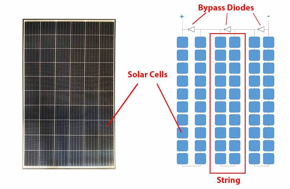
This panel consists of 60 solar cells, which are all connected in series. When exposed to sunlight (or light in general), each solar cell produces its own voltage and current.
The solar panel has 3 diodes, with each diode connected in parallel to a group of solar cells. This group of solar cells is referred to as a string. In this case, each string contains 20 cells.
PS: Below I will simplify and explain the function of these bypass diodes.
Now let’s see exactly what are the effects of shading on a solar panel.
Hotspots
When a solar panel has one or a few of its cells under shade, the shaded cells receive a very low amount of light and therefore produce a very low amount of current.
When this happens, the whole string – that contains the shaded cell – experiences a drop in current.
For example, the image below shows a string of 20 solar cells:
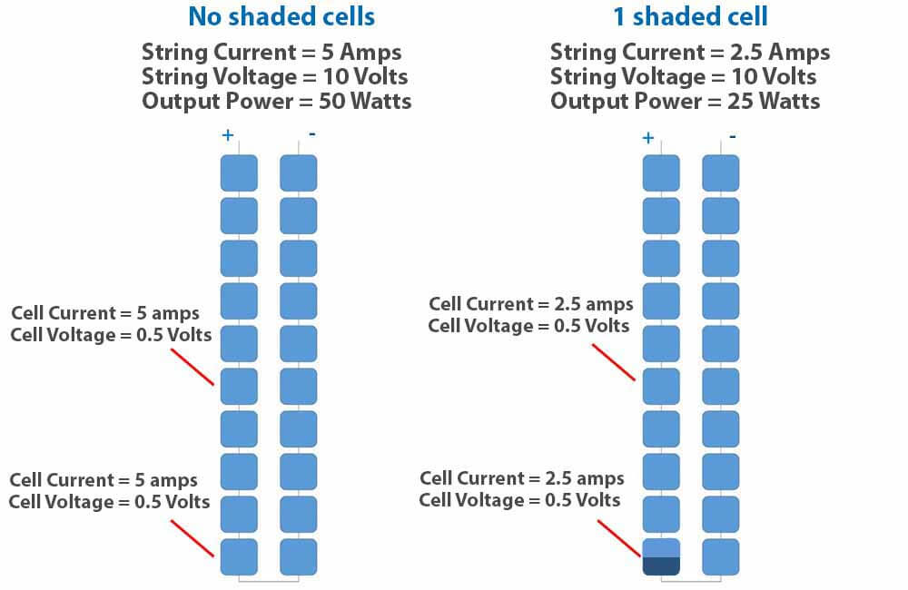
The image compares the output of the whole string when there is no shade vs when only one cell is shaded.
Basically, the current produced by the string will not exceed the current produced by the shaded cell.
Notice that only 50% of the cell is shaded, thus, it only produces 50% of the current. If the shaded cell was completely blocked from sunlight, it would produce 0 Amps, and the whole string would produce 0 Amps.
Even if the other cells are under optimal lighting conditions, their performance is limited by the performance of the shaded cell.
But where does the extra energy produced by the unshaded cells go?
This is the answer:
When a solar panel has one or a few of its cells under shade, unless the bypass diodes are activated, the shaded cells will limit the power production and will consume the extra energy produced by the unshaded cells.
So, not only does the shaded cell reduce the output of the whole string, but in doing so, it also consumes a big portion of what the other sunlit cells are producing.
As a result, the shaded cell essentially becomes a resistor that turns electrical energy into heat.
In general, hotspots occur when one or some of the cells are blocked from sunlight, this can be due to shading, dirt, leaves, etc…
For example, on the left of the image below, you can see a cell in the solar panel being covered with an object.
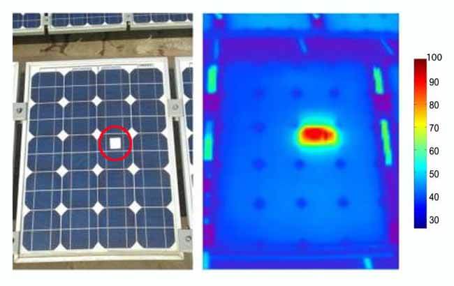
Thermal imaging on the right shows that the blocked solar cell is experiencing over 90°C (194°F).
In the long term, hot-spotting causes the overall performance of the solar panel to drop and accelerates the degradation of the affected solar cells. In some cases, it can even cause fires.
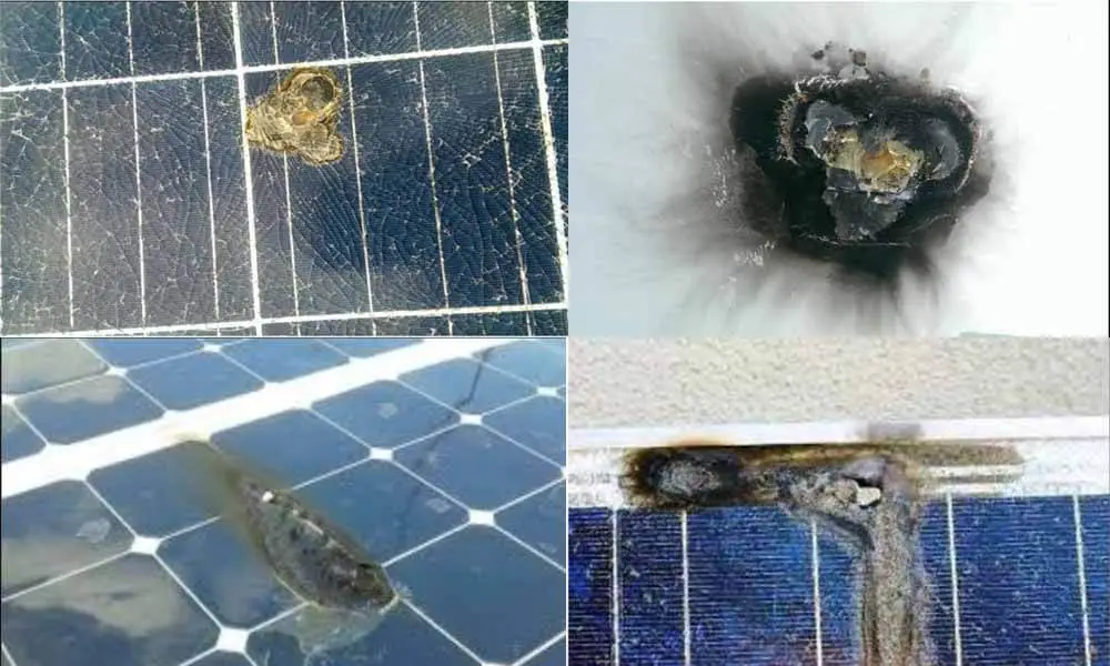
To mitigate these problems, manufacturers use bypass diodes that protect these shaded cells by ensuring that the current is flowing in the right direction.
However, in order for the bypass diodes to protect the shaded cell(s), a whole string of cells has to be bypassed.
This brings us to the next issue.
How much does partial shade affect solar panel output?
When a solar panel is partially shaded, we intuitively think that the loss in power production is going to be proportional to the shaded area of the solar panel. This is not the case.
Partial shading causes disproportional losses in energy production. In some cases, shading 10% of a solar panel can reduce its output power to 0 Watts. For example, shading the bottom 6 cells of a 60 cell solar panel can cause a 100% loss in power production.
To further understand this, let’s take a look at the internal wiring of a solar panel and how its bypass diodes work.
Most solar panels come with bypass diodes, which can be found in the junction box at the rear of the solar panel.
Depending on the manufacturer and the number of cells in the solar panel, 2 to 3 bypass diodes are used.
For example, the image below shows the junction box of a 36 cell solar panel. This solar panel has 2 bypass diodes, 1 bypass diode per 18 cells.
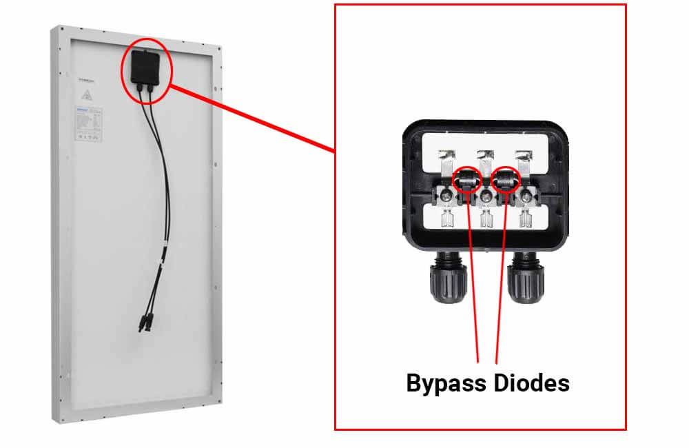
A solar panel consists of daisy-chained solar cells (solar cells in series). Each of these bypass diodes is wired in parallel with a string of cells.
For example, let’s consider a 60 cell solar panel with 3 bypass diodes:
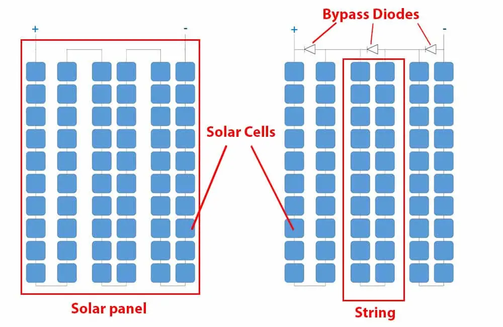
On the left of the image, you can see that all the solar cells are connected in series.
When one or a few solar cells are shaded, the power they generate is lower than the power generated by the unshaded cells.
Since all the cells are in series, the current is the same. Therefore, the difference in power translates into a difference in voltage, which activates the bypass diode in that particular string.
Bypass diodes are generally activated when there’s a 20%-30%+ difference in the current.
The unshaded cells are essentially trying to push current through the shaded cells. The shaded cells become resistive, the bypass diodes are then activated and serve as a less resistive path for the current.
This allows the current to flow in the right direction, which in turn:
- Protects the shaded cells from overheating and prevents hot spotting.
- Reduces power losses by limiting the drop in current to only one string of the solar panel.
However, the way bypass diodes are wired to the solar cells, doesn’t really allow them to select which cells to bypass.
In order to bypass the shaded cell, the diode short-circuits a whole string of cells.
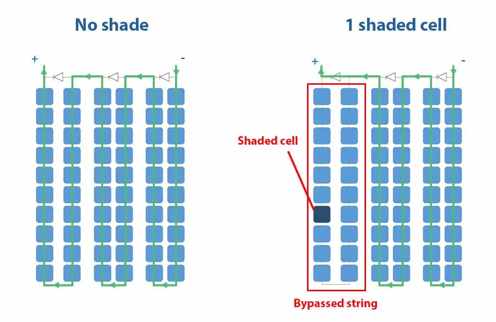
This means that one shaded cell causes the bypass diode to cut off a whole portion of the solar panel, and with it, a whole portion of the energy production.
In the example above, 20 out of 60 solar cells are bypassed because of one shaded cell. This means that around 33% of power production is lost.
This seems like a worst-case scenario, but it isn’t.
If the solar panel didn’t have bypass diodes, 100% of the power production would be lost. If it only had 2 diodes, 50% of production would be lost.
To visualize this even more, below are a few examples.
Examples of the effect of partial shading on a solar panel:
For these examples, we’re going to use a 270W solar panel. The solar panel has 60 solar cells and 3 bypass diodes, with each diode connected in parallel with 20 solar cells.
The electrical specs of the solar panel are as follows:
| Rated Power (Pmpp) | 270 Watts |
| Rated Current (Impp) | 9 Amps |
| Rated Voltage (Vmpp) | 30 Volts |
|
Voltage Drop of each Diode |
0.6 Volts |
In these examples, shading is applied to 6 cells of the solar panel. However, the location of the shade will be different in each example.
Please note that shading here refers to hard shading. This means that the shaded cells are not receiving any light (0W/m²) and therefore not producing any current or voltage.
Example 1:
For this example, shading is applied to 6 cells from the same string.
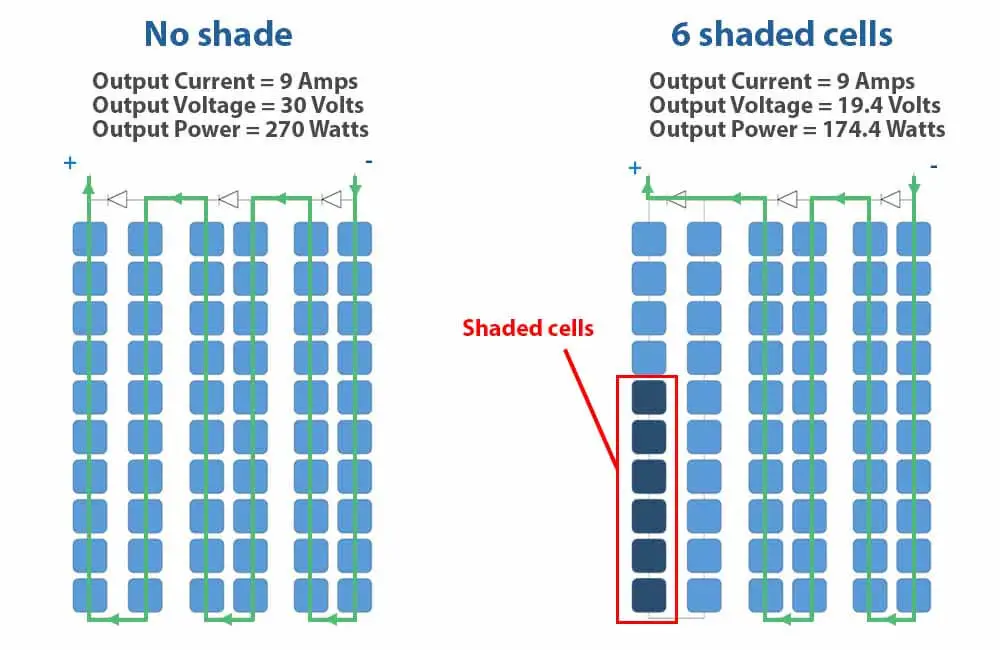
Each string is rated at 10 Volts. When the string is short-circuited by the diode, the voltage across the string is going to be 0, with a voltage drop of 0.6.
Output Voltage (Volts) = 30V – 10V – 0.6V
Output Voltage (Volts) = 19.4V
This means that when the diode is activated, the voltage across the whole module is going to drop from 30V to 19.4V.
Each of the unbypassed, unshaded cells is producing 9 Amps. Since they are connected in series and the string with the shaded cells is bypassed, the current from the whole panel is equal to 9 Amps.
The output power from the panel is then calculated as such:
Output Power (Watts) = Output Voltage x Output Current
Output Power (Watts) = 19.4V x 9A
Output Power (Watts) = 174.4W
Example 2:
For this example, shading is applied to 6 cells from 2 different strings.
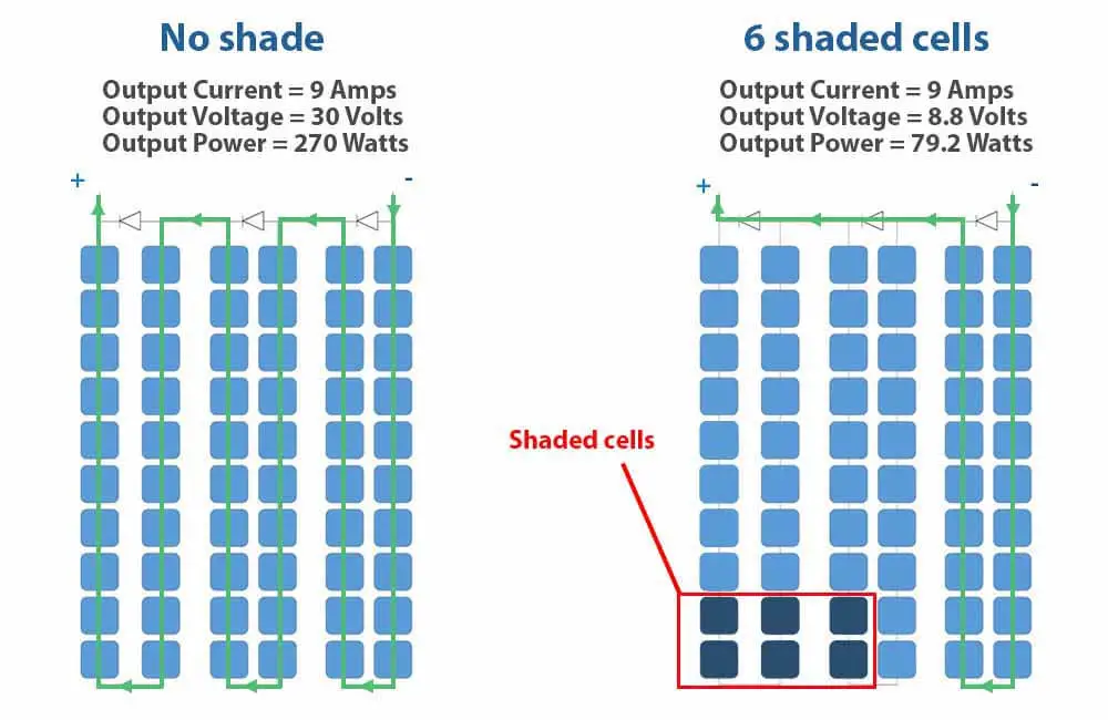
Now, 2 of our bypass diodes are activated. This means that we have 2 diode voltage drops and 2 strings are short-circuited.
Therefore our output voltage is:
Output Voltage (Volts) = 30V – 10V – 0.6V – 10V – 0.6V
Output Voltage (Volts) = 8.8V
The current from the whole panel will stay the same, 9 amps.
The output power is then calculated as such:
Output Power (Watts) = Output Voltage x Output Current
Output Power (Watts) = 8.8V x 9A
Output Power (Watts) = 79.2W
Compared to the previous example, the same number of cells are shaded, but the position of the shade is what matters.
Let take a look at an even worse scenario.
Example 3:
For this example, shading is applied to 6 cells from 3 different strings.
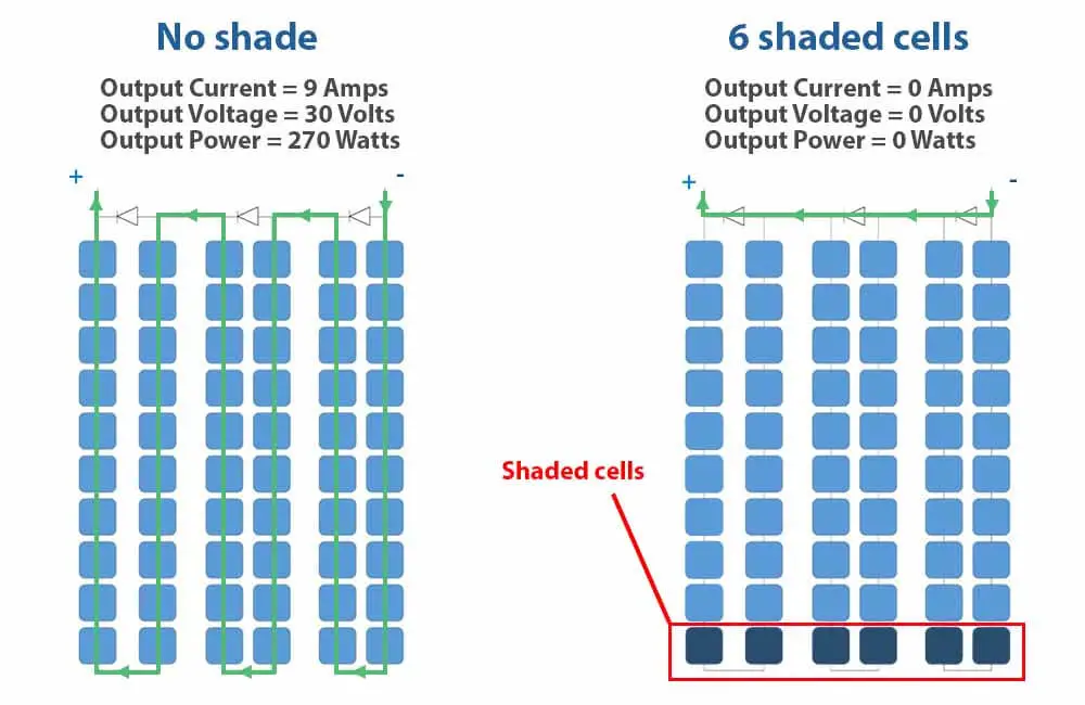
Each string from the solar panel has a couple of cells that are heavily shaded, this means that in each string, the well-illuminated solar cells are trying to push high current through the shaded cells.
which activates all the bypass diodes and the solar panel is then short-circuited and does not produce any power.
Unfortunately, this does not only apply to single solar panels. In a system of 2 solar panels or more, the effects of shading become more complicated.
The next section explains the effects of shading on strings of solar modules and solar arrays.
Solar panel shading: series vs parallel
When it comes to shading and how solar panels are wired, the most common misconception is that parallel wiring is always better. This is not 100% true.
It all depends on your setup and on the shading conditions.
To illustrate the effect of shading on the output of solar energy systems, I will use 2 solar panels, each of these solar panels has the following specifications:
| Rated Power (Pmpp) | 270 Watts |
| Rated Current (Impp) | 9 Amps |
| Rated Voltage (Vmpp) | 30 Volts |
|
Voltage Drop of each Diode |
0.6 Volts |
I will wire these solar panels in series and then in parallel, and with each setup, I will expose the system to the same degrees of shading.
In the end, we’ll compare the results and see which connection is better for shading, parallel, or series. If any.
To keep this explanation as simple as possible, I’ll assume that the systems use an MPPT charge controller.
So before we continue, the next section explains a little bit about what an MPPT does.
What is an MPPT charge controller and what does it do?
In off-grid solar energy systems, solar charge controllers were mainly used to protect the battery and solar panels. However, the newer technology of charge controllers – the MPPT solar charge controller – can do more than just protect the system.
MPPT stands for Maximum Power Point Tracking, which perfectly describes what the device does.
What an MPPT charge controller does is track both the voltage and the current for which a solar panel or a solar array produces maximum power.
In grid-tie systems, these devices are integrated into the inverter. They maximize the DC power generated by the solar energy system, the inverter then turns it into AC power and delivers it to the grid.
For the examples in this section, I will use a solar panel with the following specifications:
| Rated Power (Pmpp) | 270 Watts |
| Rated Current (Impp) | 9 Amps |
| Rated Voltage (Vmpp) | 30 Volts |
| Short-Circuit Current (Isc) | 9.65 Amps |
| Open-Circuit Voltage (Voc) | 38 Volts |
So, what do these specifications mean?
- Rated Power (Pmpp): This is the maximum power that an MPPT charge controller can get out of the solar panel at optimal sunlight (1000W/m²).
- Rated Current (Impp): This is the maximum power point current, it is the current at which the solar panel produces maximum power (Pmpp).
- Rated Voltage (Vmpp): This is the maximum power point voltage, it is the voltage at which the solar panel produces maximum power (Pmpp).
- Short-Circuit Current (Isc): This is the maximum current that the solar panel can produce. The solar panel produces this current when its positive and negative terminals are connected together.
- Open-Circuit Voltage (Voc): This is the maximum voltage that the solar panel can produce. The solar panel produces this voltage when there are no loads connected to its terminals.
We know that electrical power equals current times voltage:
Electrical Power (Watts) = Current (Amps) x Voltage (Volts)
And since the short-circuit current (Isc) and the open-circuit voltage (Voc) are respectively the maximum current and the maximum voltage that the solar panel can produce, we would intuitively think that the maximum power is the product of these 2.
However, this is not the case. The maximum power of a solar panel equals Impp times Vmpp:
Maximum Power (Pmpp) = Impp x Vmpp
To understand what this means, let’s look at the characteristics of a solar panel, which are represented using an I-V curve and a P-V curve.
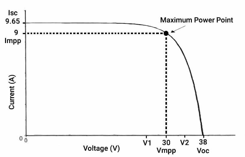
If you look at the image above, you can see that when the current is maximum (Isc), the voltage is 0. When the voltage is maximum (Voc), the current is 0.
This means that at any of these points of operations, the power produced by the panel will be 0.
The MPPT charge controller, however, controls the voltage and varies it until it finds the highest value of power. This value is referred to as the Maximum Power Point.
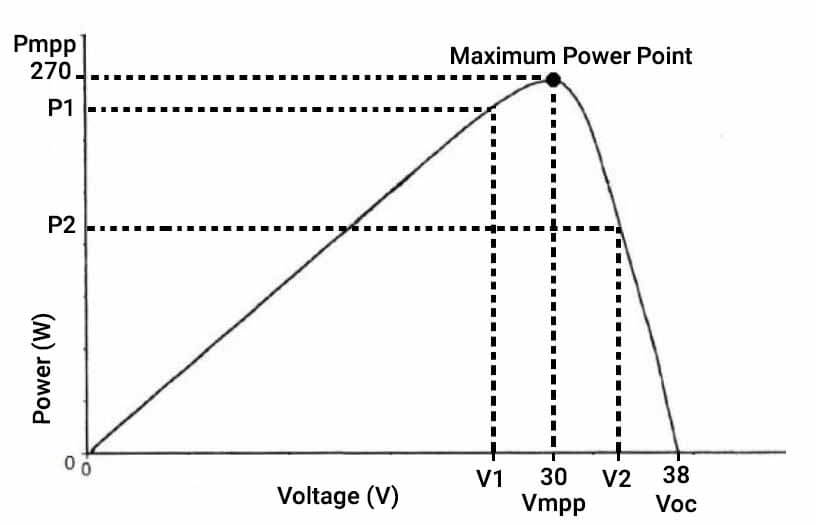
For example, at the voltage V1 (approx. 26 volts), the current is approximately 9.5 Amps, and the output power P1 is approximately 250 Watts at these voltage and current points.
At the voltage V2 (approx. 35 volts), the current is approximately 5 Amps, the output power P2 is 175 watts at these voltage and current values.
However, at the voltage Vmpp (30 Volts), the current is 9 amps, and the output power is maximal at 270 Watts.
Once the MPPT finds this point, it maintains the voltage and the current at the solar panel, and therefore maintains maximum power production.
So, what does this have to do with solar panel shading?
Let’s find out.
Effect of shade on series solar panels
When 2 solar panels are connected in series, the current stays the same while the voltage becomes the sum of the 2 voltages of the solar panels.
For example, let’s consider 2 of the solar panel used in the previous example.
Each panel has 60 cells these specifications:
| Rated Power (Pmpp) | 270 Watts |
| Rated Current (Impp) | 9 Amps |
| Rated Voltage (Vmpp) | 30 Volts |
| Short-Circuit Current (Isc) | 9.65 Amps |
| Open-Circuit Voltage (Voc) | 38 Volts |
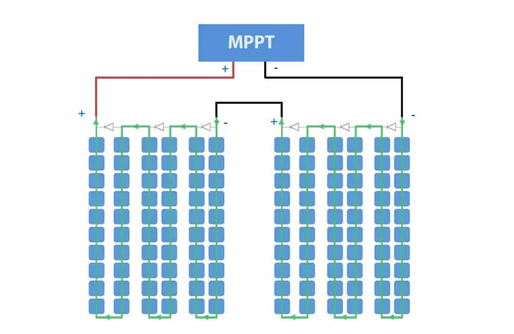
Wired in series, these 2 panels would essentially make a bigger solar panel, with these specifications:
| Rated Power (Pmpp) | 540 Watts |
| Rated Current (Impp) | 9 Amps |
| Rated Voltage (Vmpp) | 60 Volts |
| Short-Circuit Current (Isc) | 9.65 Amps |
| Open-Circuit Voltage (Voc) | 76 Volts |
Please note that each string (20 cells) has a voltage of 10 Volts. And if activated, each diode will cause a 0.6 Volt voltage drop.
Here are 3 examples that visualize how 2 series solar panels are affected by shade.
Example 1:
For the 1st example, shade is applied to a single solar cell. The shade is applied to 50% of the cell, so it only produces half of the current:
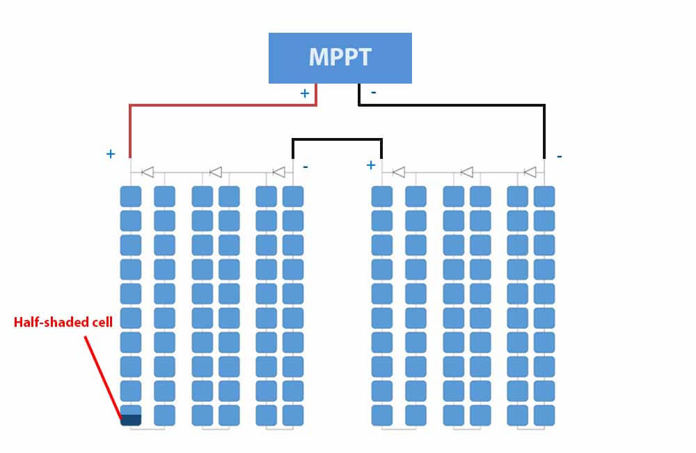
This will drop the current in both solar panels to 50%, which should trigger one bypass diode. However, before activating the diode, the MPPT needs to make sure it finds the highest output power possible.
With this update, the MPPT is going to search for the new Maximum Power Point. It essentially needs to choose between 2 operating points:
Point 1: Diode activated and solar panel operating at the maximum current (Impp).
This means that the current flowing through the solar panels is 9 Amps.
The difference between this current and the current produced by the half-shaded cell will trigger the bypass diode, and the voltage becomes:
Output Voltage (V) = 60V – 10V – 0.6V
Output Voltage (V) = 49.4 Volts
The output power at this point of operation is:
Output Power (W) = 49.4V x 9A
Output Power (W) = 444.6 Watts
Now let’s look at the 2nd operating point.
Point 2: Diode deactivated and solar panel operating at 50% current.
At this point, no bypass diode is activated, the MPPT will operate at 60 Volts and the current is 4.5 Amps (50% of 9 Amps). The output power at this point of operation is:
Output Power (W) = 60V x 4.5A
Output Power (W) = 270 Watts
At the 1st point of operation, the 2 solar panels produce the most power. Therefore, the MPPT will operate at maximum current and will bypass the shaded cell.
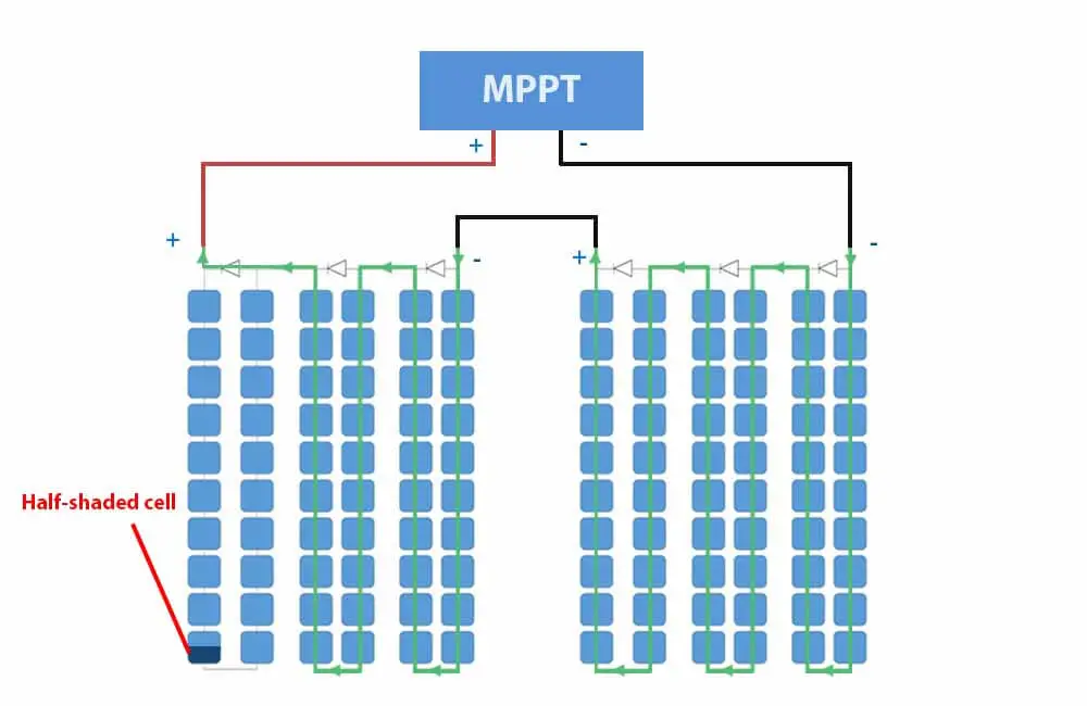
If the shaded solar panel didn’t have bypass diodes, the whole string would operate at point 2 (60V and 4.5A), half of the production would be lost. Whereas with bypass diode we only lost about 18% of its power output.
Now let look at a more complicated example with more severe shading conditions.
Example 2:
For this example, we’re going to shade half of 8 cells at the bottom. These cells belong to 4 different strings:
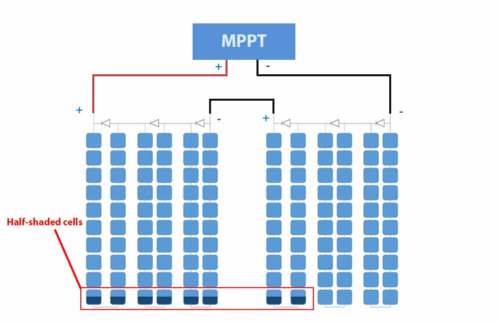
The cells are 50% shaded, which means the MPPT has to choose from 2 operating points:
- Bypass diode activated, and 100% of the current is produced.
- Shaded cells are left unbypassed, and only 50% of the current is flowing through the solar panels
Point 1: Diode activated and solar panel operating at maximum current (Impp).
At this point of operation, the current is 9 Amps. However, 4 bypass diodes are activated and 4 strings (80 cells) are short-circuited. The voltage across the 2 solar panels is:
Output Voltage (V) = 60V – 10V – 0.6V – 10V – 0.6V – 10V – 0.6V – 10V – 0.6V
Output Voltage (V) = 17.6 Volts
The output power at this operating point is:
Output Power (W) = 17.6V x 9A
Output Power (W) = 158.4 Watts
Now for the 2nd point of operation.
Point 2: Diode deactivated and solar panel is operating at 50% current (50% of Impp).
At this point, the current is 4.5 Amps, and the voltage across the solar panels remains the same (60V).
The output power is:
Output Power (W) = 60V x 4.5A
Output Power (W) = 270 Watts
In this particular example, the MPPT will operate at 50% of the current as it results in higher output power.
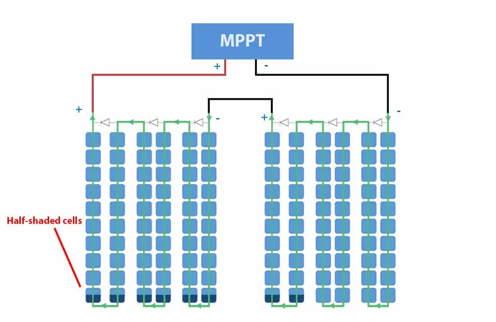
If the system didn’t have an MPPT charge controller, the system would be forced to operate at 17.6 Volts and 70% of production would be lost.
Whereas with an MPPT, the system only lost 50% of power production.
Furthermore, if the system used a PWM charge controller and was hooked to a 12V battery, the solar panels would have to operate at battery voltage (13.6 to 14.4 Volts).
Related: How does an MPPT charge controller work
Example 3:
For this example, we’re going to 100% shade one of the solar panels.
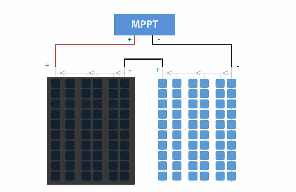
The cells in the solar panel on the left are all equally shaded and produce a negligible amount of current. For simplicity, let’s say the current production is 0 in these cells. We’ll also assume that the shading is not heavy enough to reduce the voltage of the shaded panel.
On the other hand, the cells from the other panel are not experiencing any shading and are producing 9 amps.
Point 1: Diode activated and solar panel operating at maximum current (Impp).
At this point of operation, the current is 9 Amps. However, 3 bypass diodes are activated and 3 strings (60 cells) are short-circuited. The voltage across the 2 solar panels is:
Output Voltage (V) = 60V – 10V – 0.6V – 10V – 0.6V – 10V – 0.6V
Output Voltage (V) = 28.2 Volts
The output power at this operating point is:
Output Power (W) = 28.2V x 9A
Output Power (W) = 253.8 Watts
The system here operates as if there was only one solar panel. However, the output is slightly lower than that of one solar panel due to the voltage drop caused by the bypass diodes.
The MPPT will operate at this point, because at the 2nd point of operation – where the diodes are deactivated -, the current would be 0 and so would the output power.
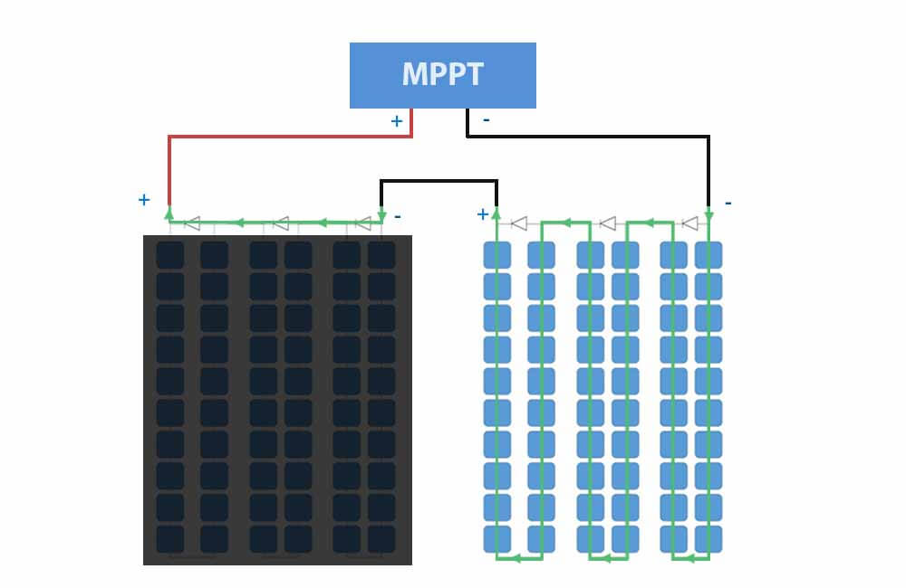
If the shaded panel was not equipped with bypass diodes, the output current would be limited to 0 Amps.
Now let’s look at the exact same shading conditions and their effect on a system that is parallel wired instead of series.
Effect of shade on parallel solar panels
In order to compare the shading effects on series vs parallel solar panels, we’ll use the same solar panels, the same shading examples, but we’ll change the wiring so it is a parallel connection.
So the specifications of each solar panel are the same as before:
| Rated Power (Pmpp) | 270 Watts |
| Rated Current (Impp) | 9 Amps |
| Rated Voltage (Vmpp) | 30 Volts |
| Short-Circuit Current (Isc) | 9.65 Amps |
| Open-Circuit Voltage (Voc) | 38 Volts |
A parallel connection means connecting the positives together and the negatives together.
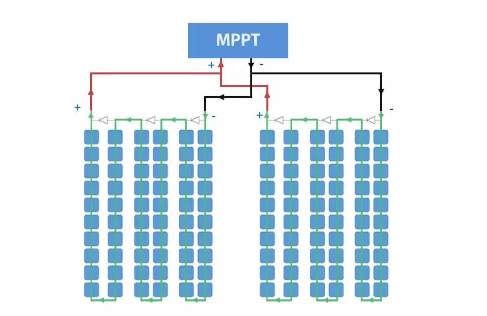
Wired in parallel, these 2 panels would make up a solar array. Without any shading, the specifications of the solar array are as follows:
| Rated Power (Pmpp) | 540 Watts |
| Rated Current (Impp) | 18 Amps |
| Rated Voltage (Vmpp) | 30 Volts |
| Short-Circuit Current (Isc) | 19.3 Amps |
| Open-Circuit Voltage (Voc) | 38 Volts |
Notice that the current becomes the sum of the 2 solar panels, while the voltage stays the same.
Now let’s test this new setup.
Example 1:
In this example, we’ll shade 50% of one cell from one of the panels.
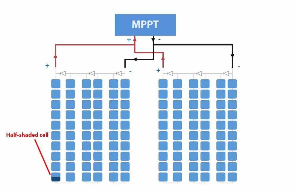 The difference between series and parallel setups is that the solar panels don’t need to produce the same current. However, they are bound by the voltage across the terminals of the MPPT.
This means that the solar panels will have the same voltage no matter what, but each solar panel will produce its own electrical current.
Point 1: Diode deactivated and solar panels operating at Vmpp.
At this point, the MPPT will force both solar panels to operate at 30 Volts.
This means that the bypass diode will not be activated and the solar panel with the shaded cell, will operate at 50% current (4.5 Amps).
However, the unshaded solar panel will still operate at 100% current (9 Amps). The resulting power is:
Output Power (W) = P1 + P2
Output Power (W) = (30V x 4.5A) + (30V x 9A)
Output Power (W) = 405 Watts
P1 refers to the power produced by the shaded solar panel, and P2 to the power produced by the unshaded panel.
Point 2: 1 Diode activated and the solar panels are operating at the voltage of the shaded solar panel.
At this point, the MPPT will force both solar panels to operate at the voltage of the shaded panel, which is:
Output Voltage (V) = 30V – 10V – 0.6V
Output Voltage (V) = 19.4V
At this voltage, the shaded panel is operating at its Impp (9 amps).
The unshaded panel will operate at a slightly higher current than its Impp and closer to its short-circuit current.
If we check the I-V curve above, we can see that the unshaded panel will operate at about 9.4 Amps.
Output Power (W) = P1 + P2
Output Power (W) = (19.4V x 9A) + (19.4V x 9.4A) = 356.96 Watts
The output power is higher when the diode is deactivated, so the MPPT will operate at Vmpp.
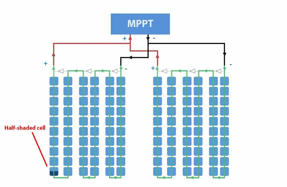
Example 2:
In this example, we’re going to shade half of 8 cells:
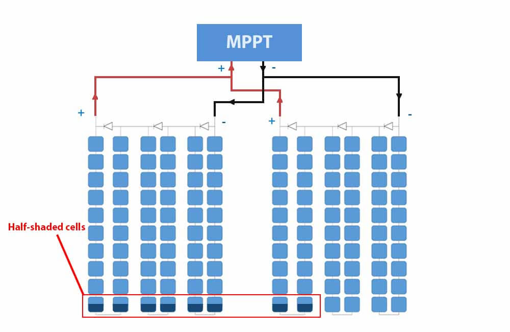
Point 1: Diodes deactivated and the solar panels are operating at Vmpp
at Vmpp, both panels will be operating at 4.5 Amps:
Output Power (W) = P1 + P2
Output Power (W) = (30V x 4.5A) + (30V x 4.5A)
Output Power (W) = 270 Watts
Point 2: 1 Diode activated and solar panel operating at 19.4
At this point, one diode from the panel on the right is activated and the voltage becomes 19.4 (30 – 10 – 0.6). At this voltage, the unshaded solar panel will operate at its Impp (9 Amps).
At 30 Volts the current of the shaded solar panel is now 4.5 Amps. At 19.4 Volts, its current is closer to its new short-circuit current. So somewhere around 4.7 Amps.
Output Power (W) = (19.4V x 4.7A) + (19.4V x 9A)
Output Power (W) = 265.78 Watts
At 30V, the system will produce the most power. Therefore, no diodes are activated the MPPT will operate at Vmpp.
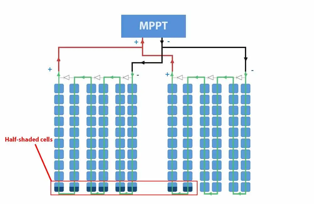
Now for a more extreme shading condition.
Example 3:
Same as the 3rd example from the series setup, one of the parallel panels is completely shaded.
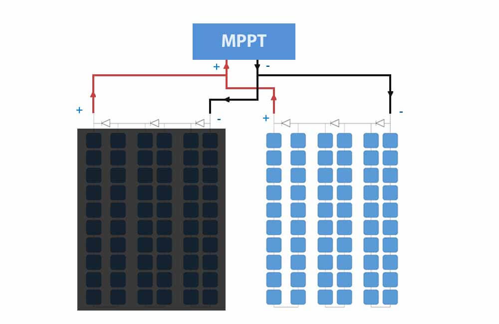
The solar cells on the left are all equally shaded, the current will drop to almost 0 and the voltage will not be affected much.
Since there is no difference in current production between these shaded cells, none of the bypass diodes will be activated.
Therefore, the MPPT will operate at Vmpp (30V).
At 30 Volts, the shaded panel is producing negligible current (0 Amps). On the other hand, the good solar panel is producing 9 Amps:
Output Power (W) = P1 + P2
Output Power (W) = (30V x 0A) + (30V x 9A) = 270W
The system is reduced to one working solar panel. Compared to a series setup, where the bypass diodes had to activate, there are no voltage drops here and the output power is slightly higher.
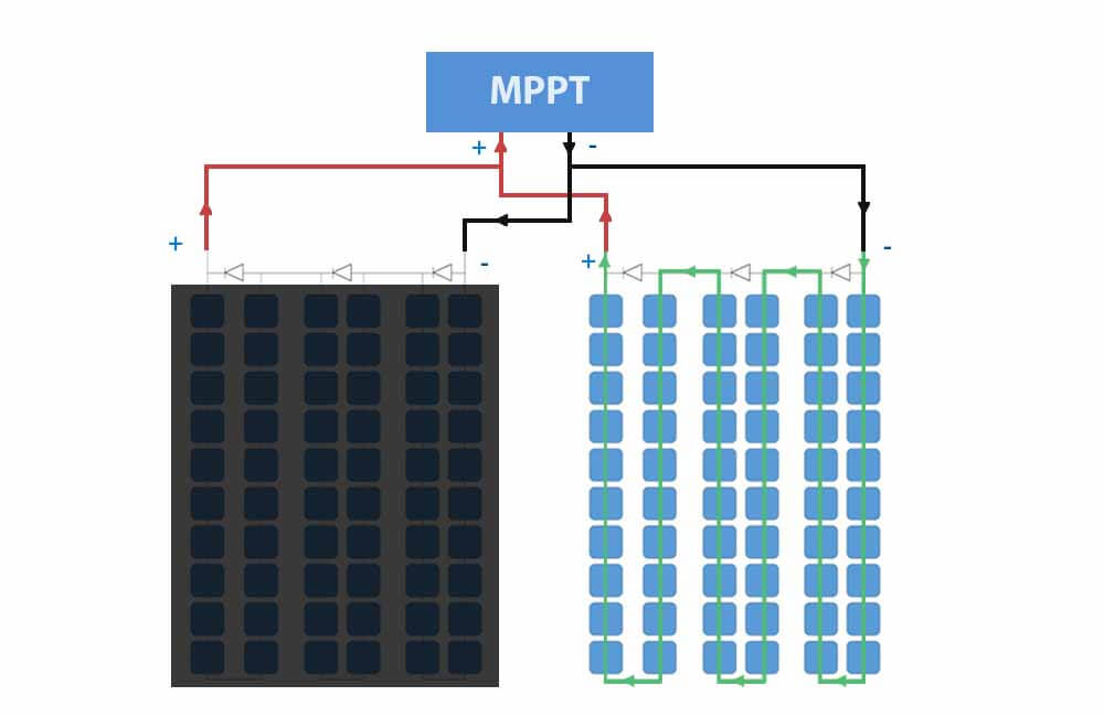
Please note that if the shading is hard enough to reduce the voltage of the shaded panel, it will start consuming power from the unshaded panel. In this case, a blocking diode would be needed.
Blocking diodes are not to be confused with bypass diodes. Below, in the shading solution section, I explain what blocking diodes are and how they can be used to mitigate the effects of shading.
Below, in the shading solution section, I talk about the use of blocking diode
The purpose of these examples was to show that with the right solar panels and charge controller, there isn’t that much difference in how you wire your solar panels.
There are just too many possibilities to say which type of connection is better.
However, in general, it is safe to say that parallel wiring is better if the bypass diodes are not working. And series wiring is better if the system doesn’t use an MPPT.
Now let’s see what techniques or devices we can use to mitigate shading effects.
Solar panel shading solutions: how to mitigate the effects of shading?
Solar panel shading is not an issue that you can solve, if the shading is there, power losses are going to be there.
However, in this section, I will talk about a few solutions that can help you mitigate these losses.
To simplify and to avoid confusion, I will discuss solutions for off-grid and grid-tie systems separately.
But first, let’s take a look at a type of solar panel that doesn’t reduce output with minor shade as much as regular solar panels.
Please note that the solutions I suggest here don’t take into consideration your particular setup or shading conditions. However, these suggestions might set you in the right direction.
Best solar panels for partial shade: Half-cut solar panels
An ideal way of using bypass diodes would be to have one for every solar cell instead of every solar string. But there are too many technical implications to this and it would simply make solar panels much more expensive.
However, manufacturers are starting to adopt a new way of making solar panels. These solar panels have the same number of bypass diodes but are wired in a way that allows them to operate better in partial shading.
These panels are called half-cut cell solar panels or half-cut solar panels.
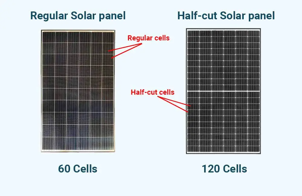
Half-cut cell solar panels like the Q.PEAK DUO series from Q Cells or the LR4-60HPH from LONGi Solar have 6 strings of cells instead of 3.
Every 2 strings are wired in parallel with each other, and between every 2 strings, a bypass diode is connected in parallel with both.
The video below explains why this technology is better equipped for shading:
With this technology of solar panels, the power losses are still going to be disproportional, but compared to a regular solar panel, the effects of shading are mitigated.
Now let’s see how we can further mitigate the effects of shading using other system components.
Solar panel shading solutions for Off-grid systems:
Use an MPPT solar charge controller for better power production
Almost every solar panel out there has bypass diodes. When shading occurs, and a difference in current is created, bypass diodes are naturally activated. Which in severe shading conditions is helpful.
However, the problem with bypass diodes is that they’re only activated if the voltage is low enough.
For example, consider a solar panel with 3 bypass diodes and an optimal operating voltage of 30 Volts. If one bypass diode is activated due to partial shading, the voltage is reduced to around 20 Volts. And the diode only stays activated if the solar panel operates at voltages below 20 Volts.
If the solar panel operates at 24V for example, the current produced by the panel will be equal to the current produced by the shaded cell(s).
- With an MPPT, this solar panel will only operate above 20V if it’s going to produce more power.
- Without an MPPT, the voltage is determined by the load (Battery).
To visualize this, I’m going to use a solar panel with the following specs:
| Rated Power (Pmpp) | 270 Watts |
| Rated Current (Impp) | 9 Amps |
| Rated Voltage (Vmpp) | 30 Volts |
| Short-Circuit Current (Isc) | 9.65 Amps |
| Open-Circuit Voltage (Voc) | 38 Volts |
Same as the examples above, this is a 60 cell solar panel that can produce 270 Watts under optimal sunlight.
Now, let’s say the solar panel is hooked to a 24V AGM battery bank with a charging voltage of around 26 Volts.
Next, I’ll apply partial shading at the bottom of the panel and compare its output with, and without an MPPT charge controller.
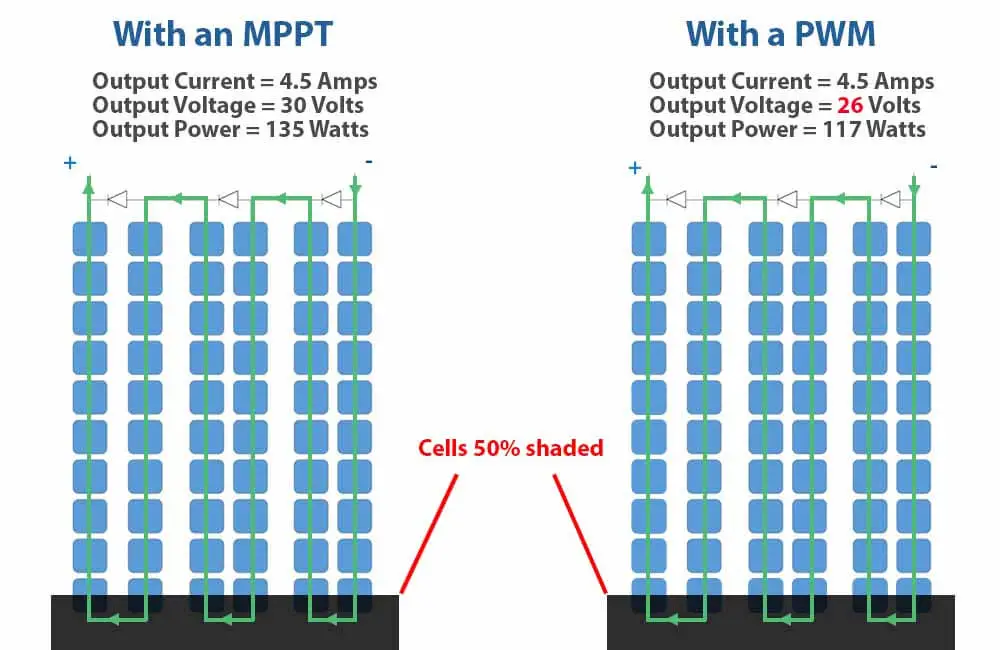
The shade covers 50% of the bottom cells and therefore limits the current to 50% of its initial value. Without the shade, the solar panel is supposed to produce 9 Amps. But with the shading applied, the current becomes 4.5 Amps.
On the right side of the image, where a PWM charge controller is used, the solar panel operates at battery voltage, which in this case is 26V. At 4.5 Amps and 26 Volts, the output power is 117 Watts.
However, on the left side, the MPPT keeps testing voltages and finds that the solar panel can still produce half of its rated current at 30 Volts. The output power at this voltage is 135 Watts.
Since this output is higher than the alternative (0 Watts), the MPPT will operate at this voltage (30 Volts).
Compared to the output from the PWM charge controller, in this particular example, the MPPT was able to get out around 20 more watts from the solar panel.
If the solar panel was hooked to a 12V battery via a PWM, which shouldn’t be done anyway, the solar panel would operate at about 13V and would produce around 60W. In this case, with an MPPT, the solar panel would still produce 135 Watts.
Here are a few links to articles and resources where you can read up more on solar charge controllers:
- MPPT charge controller calculator
- How to size an MPPT charge
- What are solar charge controllers?
- What does an MPPT solar charge controller do?
Now for the next tip.
Use one MPPT for each string of panels
If your solar energy system consists of multiple parallel strings, instead of using one big MPPT for all the panels, you can use smaller MPPTs for different strings.
Because contrary to what many people say, in extreme shading conditions, parallel wiring can actually be worse than series wiring.
In a multiple string setup, the voltage across all the strings has to be the same at all times. In severe shading conditions, where a solar panel is completely blocked from sunlight, its voltage becomes very low.
For example, if the setup includes 2 solar panels wired in parallel, and one of the panels is severely shaded, the MPPT will essentially have 2 options:
- Operate at the voltage of the shaded panel: Here the output of the unshaded panel will drop significantly, which means the global output will be lower than it should be.
- Operate at the voltage of the unshaded panel: Here the unshaded panel will start pushing current through the shaded cell
The MPPT doesn’t really care about the physical implications of the point at which it operates, it only cares about finding the highest output power possible.
In severe shading conditions, where only one of the panels is affected, the MPPT will most likely operate at the second point.
This means that the unshaded panel will reach maximum output, but the shaded panel will consume some of that output and therefore reduce the global output of the system.
This is because a solar panel that is completely blocked from sunlight, will have a very low voltage. And when 2 voltage sources are connected in parallel, the one with the higher voltage will push current through the one with the lower voltage.
In any case, a smaller MPPT for each string of panels will ensure that each string has an independent output.
This will also allow you to have different tilt angles or directions for each string.
Furthermore, the cost of doing this is 50% more at most.
For example, this 20A MPPT charge controller from Victron costs about $160. While this 10A MPPT from the same company costs about $100. 2 of these 10A controllers would only cost 25% more, but would allow the strings to operate independently.
Use blocking diodes in your parallel setup
This solution is common in parallel setups and is mainly used to prevent a shaded solar panel from consuming current.
For example, if we have 2 solar panels wired in parallel and one is extremely shaded, its voltage becomes very low. In such conditions, with one MPPT controller, the shaded panel will actually start consuming a portion of the current produced by the good solar panel.
This is because the unshaded panel applies a voltage that the shaded panel cannot reach on its own. When this happens, the current is pushed through the shaded solar panel.
As mentioned above, diodes are very useful when it comes to controlling the direction of the current. For example, bypass diodes are connected in parallel with solar cells to provide a correct path for the current.
On the other hand, Blocking Diodes are wired in series with a solar panel or a string of solar panels. This ensures that current can only go from the string to the charge controller, and not from one string to the other.
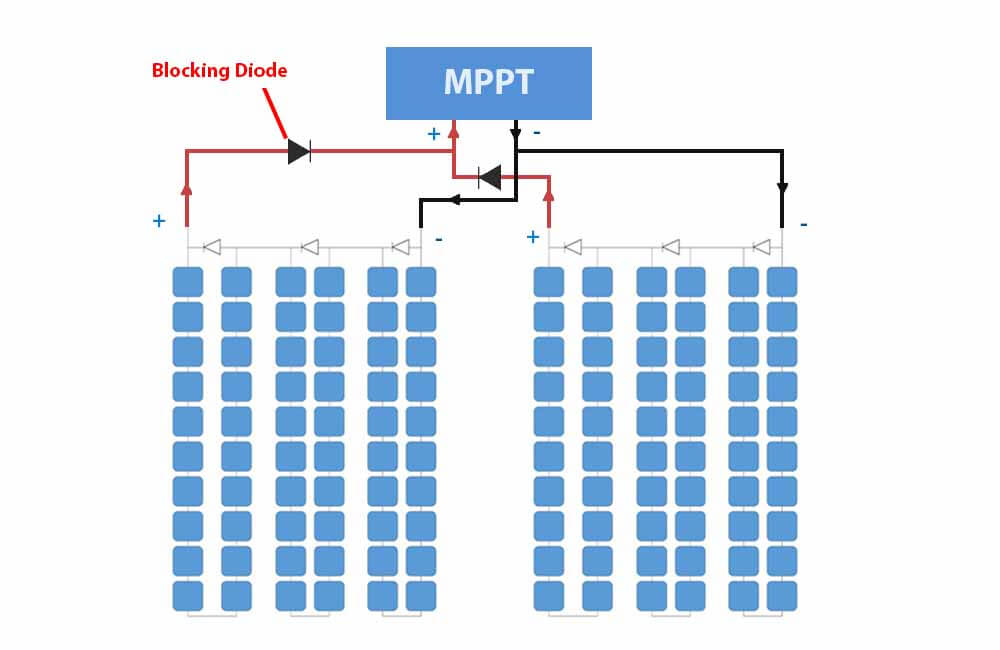
However, although blocking diodes are quite helpful, it’s best if they’re only used if the shading is reoccurring. Because with blocking diodes you’ll have a permanent voltage drop.
As mentioned above, when current is flowing through it, a diode will typically cause the voltage to drop by 0.5V-0.7V.
The better kind of diodes for these applications are Schottky diodes. A Schottky diode has a voltage drop of only about 0.15 V, which is quite an improvement.
Now let’s talk about shading solutions for Grid-tie systems.
Solar panel shading solutions for Grid-tie systems:
In grid-tie solar systems, the setup is a bit different than Off-grid installations. However, the same principles apply.
Here are a few tips on how you can maximize the output of your system if shading is unavoidable.
Use string inverters with more than one MPPT
As mentioned above, MPPTs are a great plus whether or not your solar panels are experiencing shading.
In grid-tie solar systems, MPPTs are integrated into the inverter. The DC power from the solar panels is optimized and maximized before it is turned in AC power and fed to the grid.
It is only logical that the more MPPT inputs an inverter has, the better optimization it can do.
For example, while the Fronius Primo 6.0-1 has 2 MPPT inputs, SMA’s Sunny Boy 6.0 has 3 MPPT inputs. Both of these inverters are designed for 6 Kw systems, but SMA’s has the advantage when it comes to optimizing string outputs independently.
Now, what if the optimization can be more independent?
Well… it can!
Use MLPEs for your solar energy system:
MPLE stands for Module Level Power Electronics. These devices are installed at the rear of solar panels and maximize power production at the panel level.
This means that the solar panels are completely independent of each other, each solar panel has its own voltage and current.
Generally, there are 2 types of MLPEs:
DC optimizers
DC optimizers like the ones from SolarEdge or Tigoenergy, are essentially small MPPTs that connect to individual solar panels.
The optimized output from these optimizers is then connected to a central inverter, which turns DC into AC.
Microinverters
Microinverter also connect to individual solar panels, but they don’t require a central inverter. Each microinverter has an integrated MPPT and an inverter.
The solar panel produces DC power, the microinverter maximizes that power and turns it into AC power, and then feeds it to the grid.
Key takeaways:
- Solar panels can work in the shade as long as it not severe
- Shading causes disproportional power losses and can damage solar panels in the long term
- If you have shading, MPPTs can mitigate its effects
- In grid-ties systems, the more MPPT inputs an inverter has, the better.
- Consider using DC optimizers or Microinverters for your grid-tie system


Great write up on the pro’s and cons of Serial vs Parallel Solar Panels. One of the best I have read.