PWM charge controllers are probably the most used type of solar charge controller in small off-grid systems. Compared to MPPT charge controllers – another type of solar charge controller- they are very cheap and accessible.
In this article, I’ll explain what a PWM charge controller is, how it works, why you need one, and how to choose the right one.
What is a PWM charge controller why do we use it?
PWM (Pulse Width Modulation) solar charge controllers are electronic devices used in solar energy systems to protect the battery. These devices connect the solar panels to the battery to prevent it from overcharging and over-discharging.
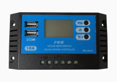
When a PWM charge controller is connected to a battery, it limits the current fed to the battery by the solar panels or drawn from the batteries by the loads.
Also, at night when the voltage of the battery is higher than that of the solar panels, the PWM charge controller prevents the solar panels from draining the battery.
But what would happen if solar panels are connected directly to the battery?
If A battery is directly connected to a solar array, 2 bad things can happen to the battery:
This is when an excessive amount of electric current is pushed through the battery. When a battery is overcharged, the excess energy translates into heat.
This can cause different reactions depending on the type of battery, but in the long term, the outcome is the same: a damaged battery.
This is when the battery keeps delivering power to the load beyond the recommended depth of discharge or even after its state of charge is at 0%. When this occurs, the chemical reactions happening inside the battery become irreversible.
Since the whole point of a battery is the reversibility of its chemical reactions, over-discharge will cause losses in battery life and capacity.
Now, let’s see how a PWM charge controller prevents these problems from happening.
How does a PWM solar charge controller work?
When a battery is charging and is almost at 100% state of charge (SoC), a PWM solar charge controller will begin to limit the amount of power delivered to the battery. This ensures the battery is maintained at full charge while also preventing it from overcharging.
In other words, PWM charge controllers regulate the power produced by the solar panels by lowering the average DC voltage when necessary. These devices control the average DC Voltage at the terminals of the battery by simply turning ON and OFF.
The image below shows what the output signal of a PWM charge controller looks like:
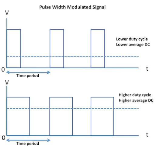
Pulse Width Modulated Voltage Signal
When the PWM controller is ON, the solar panels are connected to the battery; when OFF, the solar panels are disconnected. The period of time for which the solar panels are connected is called Duty Cycle.
The longer the duty cycle, the higher the power delivered to the battery. The length of this duty cycle depends on the battery’s state of charge.
The images below show how the voltage and current of different battery cells behave while charging.
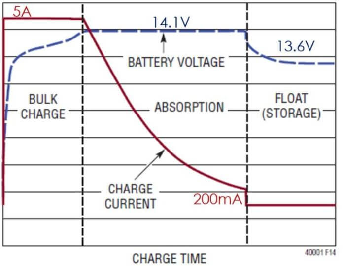
Lead-Acid battery charging voltage and current
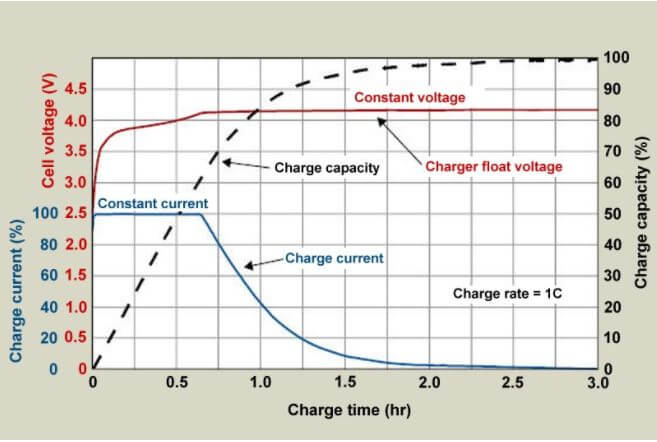
Lithium battery cell charging voltage and current
When the battery is at a low state of charge and starts charging, its voltage slowly ramps up as the PWM stays on to allow as much current as possible into the battery.
But when the battery is almost fully charged, its voltage stabilizes at a certain value (around 13.6V for 12V batteries). The PWM starts decreasing the duty cycle to maintain that certain voltage, this ensures that the battery is not overcharging.
As mentioned above: batteries are not only at risk of overcharging but also over-discharging.
For some battery types such as lithium, over-discharging means going lower than 5% or even 0% state of charge. For Lead-acid batteries, going lower than 50% SoC can be considered over-discharging. For both types, over-discharging will decrease battery capacity and life.
The image below shows the voltage vs depth of discharge for 12v lithium and lead-acid batteries.
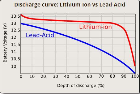
The depth of discharge (or DoD) in the image is the reverse of the state of charge (SoC).
Since there is a correlation between the state of charge and voltage, to prevent over-discharging, this time the PWM disconnects the load when the battery voltage goes lower than a certain value. This feature is referred to as Low Voltage Disconnect or LVD.
However, this is only applicable if there are small DC loads connected to the load terminals of the PWM.
If all the loads are connected to the battery through the Inverter (which is and should be connected directly to the battery), when the battery is at an unhealthy state of charge, the inverter can disconnect the battery through the LVD feature as well.
How to choose a PWM charge controller?
To choose the right PWM solar charge controller for your system you have to calculate the maximum current that your solar array can generate. This is done by multiplying the short-circuit current of your whole solar array by 1.25 (NEC’s safety factor).
For example:
Consider 2 parallel wired solar panels, and each of these panels had a short-circuit current of 5.8A. The amperage rating of the PWM charge controller can be calculated as follows:
PWM Amperage rating = 2 x 5.8A x 1.25
PWM Amperage rating = 14.5A
Once you calculate the maximum current generated by your solar array, you’ll have to find a PWM charge controller with an amperage rating higher than the calculated maximum current.
This 20A PWM charge controller would be perfect for the job.
You should also take into consideration the voltage of your system. Now, most PWM charge controllers are compatible with both 12V and 24V, so if you have a 12V or 24V system you should be okay.
However, if you have a 36V or 48V system, you’ll have to make sure the PWM charge controller you choose is designed for that voltage.
To make things easier for you, I made this PWM solar charge controller calculator. All you have to do is enter some details and the calculator will display a direct link to the best PWM controller for your system.



Hi great site, thanks for the very helpful information. I’ve just bought a 140w solar panel with a pwm charge controller or correctly named voltage regulator. My previous panel was sabotaged, hence the new purchase. However the previous panel has a fully sealed unit so based on other advice I connected my system with the inverter directly off the battery terminals. I was under the impression that this was the way to do it since the inverter has 2 AC 240v sockets and 2 USB ports on it. I see however that the voltage regulator that came with the new panel has a positive and negative connection for load. Therefore is the correct way to set my system up, to connect the inverter to the positive and negative terminals on the load on the pwm unit and run everything that way or should I just ignore the load terminals and do as before, continue connecting inverter directly to battery terminals? The reason I’m asking is because if I do it the way I’ve been doing it from the beginning, can the pwm charge controller still monitor and control the charge and the discharge to the battery when the load is coming off the inverter connected to battery as opposed to dedicated load terminals on the charge controller?
Hello there Martin! You are very welcome!
The inverter should be connected to the terminals of the battery and not to the load terminals of your charge controller.
The load terminals on the charge controller are for small DC (Direct Current) loads.
The charge controller will still be directly connected to the battery and will still be able to control and protect it using voltage readings. Also, the inverter can also disconnect the battery and protect it from over-discharging if necessary.
In any case, you SHOULD NOT connect the inverter to the load terminals of the charge controller.
Hi J
I have a 100wh solar panel on my caravan linked to manufacturer fitted PWM volt regulator which is set for my 120ah AGM battery.
Could I link an extra external 100wh portable solar panel directly to the caravan battery terminals ( with the v regulator supplied with the kit) at the same time as using the onboard system. This would be for occassional topping up when less sunny!
Thank you for your valuable and interesting articles
Best.
Peter
Hey there Peter,
I think the answer is yes, you can.
If the PWM charge controller voltage rating is compatible with that of the battery, you should be good to go.
Hope this helps.
جزاك الله خير for your excellent information.
I am a complete novice, but from your explanations, I’ve had learned the basics and my horizons have expanded
Hi I want to know if solar charger input it can be 38v and output 12v is it possible?
Hey Justice,
Yes, especially if it’s an MPPT charge controller. MPPTs are designed to convert high voltage/low current power at the input to a lower voltage/higher current power at the output.
So yes.