Solar charge controllers are rated in amps but are also limited by their maximum input voltage.
To select the right MPPT charge controller for your system, you need to answer 2 questions:
- How much voltage do you expect it to handle?
- How much current do you expect it to be able to put out?
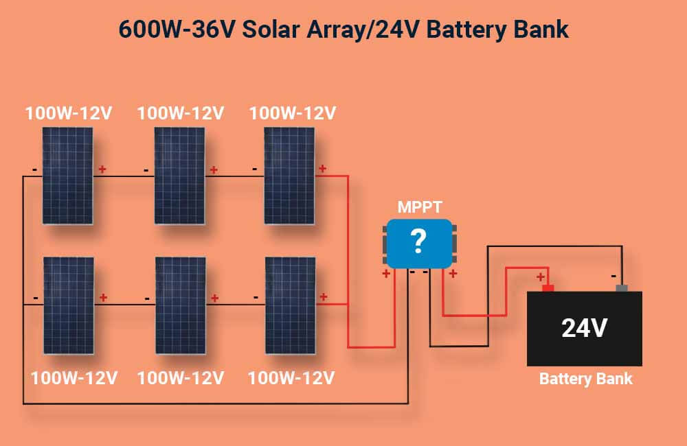
To make this guide more digestible, I will use the following system as an example:

Solar Array:
6 identical 100W-12V Monocrystalline Solar Panels from Renogy.
As shown in the image above, the panels are wired in 3S2P. This means 2 parallel strings, each string with 3 solar panels wired in series.
Battery bank:
4 identical 100 Ah 12V LiFePO4 Deep Cycle Battle Born Batteries.
The batteries are wired in 2S2P, making it a 200Ah 24V battery bank.
By the way, if you’re in a hurry you can directly use our MPPT calculator.
How to size an MPPT solar charge controller in 2 steps:
As mentioned above, solar charge controllers are designed with a maximum output current and a maximum input voltage, both of which they cannot exceed.
So the process of sizing your solar charge controller really comes down to 2 main steps:
- calculating the maximum input voltage
- calculating the maximum output current
Step 1: Calculate the maximum input voltage of the MPPT charge controller.
If the voltage from your solar array exceeds the maximum input voltage of the MPPT, the electronic circuitry inside the device could be damaged and no longer be operational.
So, before you choose an MPPT charge controller, you should be aware of how high of a voltage the MPPT should be able to deal with.
This step is especially necessary if you have multiple solar panels in series.
To that end, there are 3 questions you need to know the answers to:
- What is the open-circuit voltage on the panels?
- How many solar panels are wired in series?
- What is the lowest temperature the solar panels will be exposed to during sunlight hours?
Question 1: what is the open-circuit voltage on the panels?
Solar panels have 3 voltage characteristics:
Nominal Voltage:
This voltage is not specified by the manufacturer but was originally used to categorize solar panels and their compatibility with batteries.
A solar panel with a nominal voltage of 12V will actually put out more than 12 volts, but it is the right panel for charging a 12V battery.
Maximum Power Voltage (Vmp):
Every solar panel is tested under standard conditions, these conditions are referred to as STC.
In these tests, the manufacturer specifies the voltage for which the solar panel is operating at its rated power when connected to a load, that voltage is referred to as the Maximum Power Voltage or Vmp.
Open-circuit voltage (Voc):
Under standard test conditions, the Voc is the voltage reading from a solar panel when it’s not connected to any load.
In solar energy systems, the Voc is usually the highest voltage that a solar panel can put out.
Therefore, this is the voltage used to estimate how much of a maximum input voltage is the charge controller expected to handle.
So, where do you find the value of the open-circuit voltage on your solar panel?
You can easily find the Voc on the specifications label stuck to the solar panel.
If you can’t find the specifications label on your solar panel, try googling the model of the solar panel.
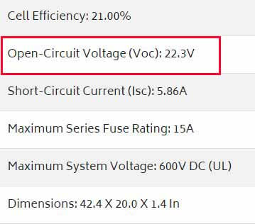
For example, in the image below you can see the technical specifications of the Renogy solar panels we’re using in the example.

So the open-circuit voltage we’re looking for is 22.3V.
If you still can’t find the voltage specifications, you can still count the solar cells on the panel. 12V panels have 36 cells, 24V panels have 72, and 20V panels have 60 solar cells.
The table below will then help you estimate the open-circuit voltage on your panel.
| Voltage (nominal) | Max Power Voltage (Vmp) | Open Circuit Voltage (Voc) |
| 12V | 17~18V | 21~23V |
| 20V | 29~31V | 37~39V |
| 24V | 34~36V | 43~45V |
However, this is just to make some estimates. You should still find the exact value of Voc on your solar panels.
Now that we know, or at least have an idea about the maximum voltage expected from a single solar panel, we should determine the maximum voltage expected from the whole array at standard test conditions.
Question 2: How many solar panels are wired in series?
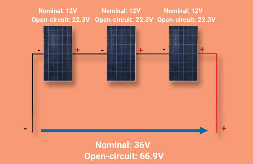
When solar panels are wired together in series (positive to negative), we refer to them as a string. The total voltage from the string is equal to the sum of the voltages of the panels.
Following our example:

In the image above, you can see 3 identical 12V solar panels wired in series.
The nominal voltage of the string is 36 volts. And the open-circuit voltage from the string is 66.9 volts.
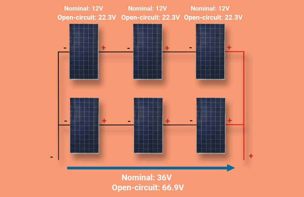
Now, let’s consider the whole solar array:

In this solar array, there are 2 parallel strings with 3 panels in each string. The solar array will produce more power and put out more amps, but the voltage is still the same.
Learn more about solar panel series-parallel connections here.
In the standard test conditions, the open-circuit voltage of our array is equal to 66.9V.
Question 3: What is the lowest temperature your solar panels will be exposed to during sunlight hours?
It might sound counterintuitive, but low temperatures cause solar panels to produce more voltage and power.
The standard test temperature for solar panels is 77°F (about 25°C). If the temperature gets lower than that, you should expect a rise in both voltage and power.
There are actually 2 ways to calculate exactly how a certain temperature value affects the open-circuit voltage and the power of your solar panel.
Both ways will give you the same results, so let’s just focus on the easier one.
The NEC 690.7(A) table below shows a set of voltage correction factors.
| Ambient Temperature (°F) | Correction Factor | Ambient Temperature (°C) |
| 68 to 76 | 1.02 | 20 to 24 |
| 59 to 67 | 1.04 | 15 to19 |
| 50 to 58 | 1.06 | 10 to 14 |
| 41 to 49 | 1.08 | 5 to 9 |
| 32 to 40 | 1.10 | 0 to 4 |
| 23 to 31 | 1.12 | -5 to -1 |
| 14 to 22 | 1.14 | -10 to -6 |
| 5 to 13 | 1.16 | -15 to -11 |
| -4 to 4 | 1.18 | -20 to -16 |
| -13 to -5 | 1.20 | -25 to -21 |
| -22 to -14 | 1.21 | -30 to -26 |
| -31 to -23 | 1.23 | -35 to -31 |
| -40 to -32 | 1.25 | -40 to -36 |
Following our example, the open-circuit voltage is 66.9V. But again, that is in standard test conditions.
Now we need to calculate how high the voltage could potentially be with a lower temperature.
For example, if I expect the lowest temperature during sunlight hours to be around 15°F, all I have to do is multiply the Voc by the corresponding correction factor:
Temperature-corrected Voc = Voc x Correction factor
Temperature-corrected Voc = 66.9V x 1.14
Temperature-corrected Voc = 76.26V
76.26V is the highest voltage that we should expect at the terminals of this particular solar array.
This value means that the solar charge controller I select needs to have a maximum input voltage greater than 76.26V.
Now let’s see how many Amps our charge controller needs to be able to put out.
Step 2: Calculate the maximum output current of the MPPT charge controller
To figure out the amount of current that our solar charge controller needs to be able to put out, all we have to do is use the electric power equation.
Watts = Volts x Amps
Amps = Watts ÷ Volts
But which wattage and voltage are we going to use for this equation?
The wattage: the maximum power (in Watts) that the solar panels are expected to produce.
The voltage: the Volts required to charge the battery bank.
So the 2 questions here are:
- How much maximum power are the panels expected to produce?
- What is the charging voltage of the battery bank?
Let’s answer each of these questions.
Question 1: How much power to expect from the solar array?
In our example, we have 6 solar panels and each of them is rated at 100W. So the total wattage of the array is 600W.
However, we should also factor in the rise in power production when the temperature goes below 77°F (STC).
The same NEC correction factors could be used to calculate the expected rise in power production.
Using the same low-temperature example I used above:
Maximum Power = 600W x Correction factor
Maximum Power = 600W x 1.14
Maximum Power = 684W
So 684W is the wattage we’ll use in our calculations.
Question 2: What is the charging voltage of the battery bank?
Just like solar panels, batteries have different voltage characteristics. The 12V, 24V, or 48V we use to refer to a battery or battery bank is the nominal voltage.
But the actual voltage of a battery depends on its State of Charge (SoC). For example, the voltage of a fully charged Lithium 12V battery is about 13.6 Volts. However, when the same battery is at 0% SoC (fully depleted), its voltage drop to about 10 Volts.
Either way, the MPPT tracks this battery voltage and applies a slightly higher voltage to push current into the battery.
The exact voltage applied by the MPPT will depend on the battery’s state of charge, and since MPPTs decrease the voltage and increase the current from the solar panels by the same ratio, the lowest voltage at the MPPT’s output means the highest current at its output.
In other words, to calculate the Output Current rating required in our MPPT, we need to use the lowest voltage at which the charge controller is going to charge the battery.
Here’s a table that shows the approximate charging voltage for battery banks with different nominal voltages:
| Nominal Voltage | Charging Voltage |
| 12V | 12 V – 14.4 V |
| 24V | 24 V – 28.8 V |
| 36V | 36 V – 43.2 V |
| 48V | 48 V – 57.6 V |
Following our example:
The battery bank is 24V nominal, so its lowest charging voltage is approximately 24V.
Now that we have the wattage and the voltage, we can calculate the amperage rating (or Output Current rating) of our solar charge controller:
Amperage rating (Amps) = 684W ÷ 24V
Amperage rating (Amps) = 28.5A
So, the MPPT charge controller we would need for the system from our example needs to be able to put out 28.5 Amps of current and have a maximum input voltage greater than 76.26V.
An EPEVER 30A MPPT charge controller can output up to 30 Amps of current at its output, and handle up to 100 Volts of voltage at its input.


Thank you Younes,
Your website is wonderful, learned a lot from your articles about solar systems.
thanks again.
Great series of articles. Clearest explanation I’ve seen, helped me so much. Thank you. Dee.
Thanks for your explanation, I have just simple question.. is it important to take care about the maximum charging current for the battery could handle when we choose mppt charge controller.. thanks in advance
Hey there Yasir,
Yes, most batteries have a maximum charging current that you should take into consideration.